
Fabricated floor slab with connecting component

A technology of connecting components and assembly, which is applied in the direction of floors, building components, structural elements, etc., can solve the problems of using a large number of I-beams, complex assembly process, and low assembly level, so as to achieve low construction cost and low labor intensity , The effect of reducing the weight of the floor

Inactive Publication Date: 2020-12-11
HUBEI SHENZHOU BUILDING MATERIAL
View PDF14 Cites 0 Cited by
  • Summary
  • Abstract
  • Description
  • Claims
  • Application Information

AI Technical Summary

Problems solved by technology

[0008] However, there are certain defects in the construction methods of the above-mentioned several floor slabs.
The first method requires a lot of cast-in-place operations, and the overall degree of assembly is low
The second method also requires certain cast-in-place operations, and at the same time, the assembly process is more complicated and the construction is more difficult.
The third method needs to use a large amount of I-beam, the overall steel consumption is relatively large, and the cost is relatively high

Method used


Image

  • Fabricated floor slab with connecting component
  • Fabricated floor slab with connecting component
  • Fabricated floor slab with connecting component

Examples


Embodiment 1

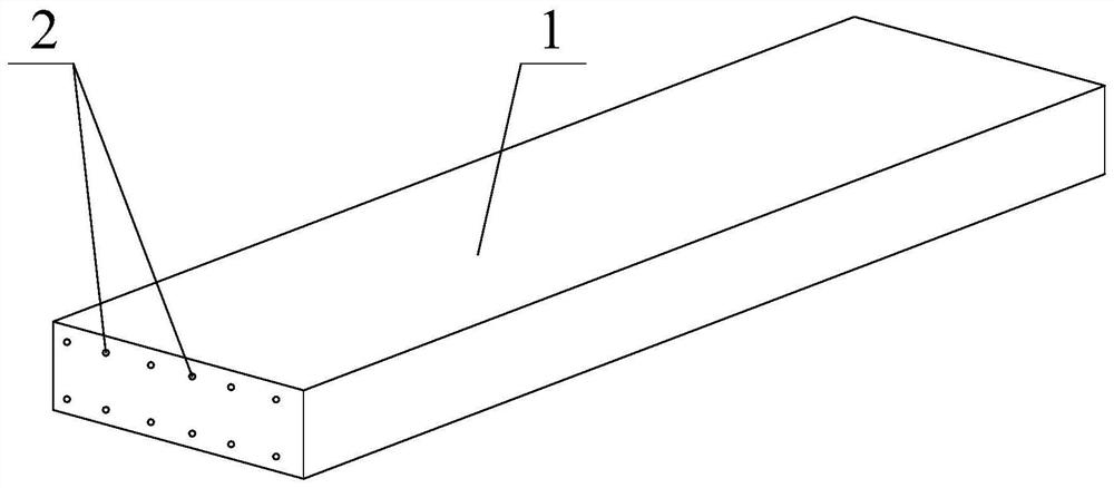
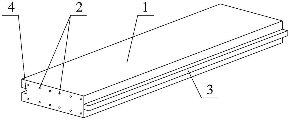
[0056] Such as figure 2 As shown, the prefabricated floor slab with connecting members in this embodiment includes a load-bearing steel truss 2 and a lightweight concrete slab 1 , and the steel truss 2 is embedded in the lightweight concrete slab 1 . The connectors in this embodiment use connecting steel bars or connecting steel plates, which are directly welded to both ends of the steel bar truss 2 after the steel bar truss 2 is fabricated.

[0057] The floor slab of this embodiment is also provided with connecting members for splicing. The connecting member in this embodiment is a mortise and tenon member, and the mortise and tenon member includes grooves 4 and flanges 3 arranged on both sides of the lightweight concrete slab 1 and matched with each other. For the present invention, all more than three hundred kinds of mortise and tenon structures in the prior art can be applied to the present invention.

[0058] This embodiment can be manufactured by using the manufactur...

Embodiment 2

[0063] The prefabricated floor slab with connecting members in this embodiment includes a load-bearing steel bar truss 2 and a lightweight concrete slab 1 , and the steel bar truss 2 is embedded in the lightweight concrete slab 1 . The lightweight concrete slab 1 is an autoclaved aerated concrete slab.

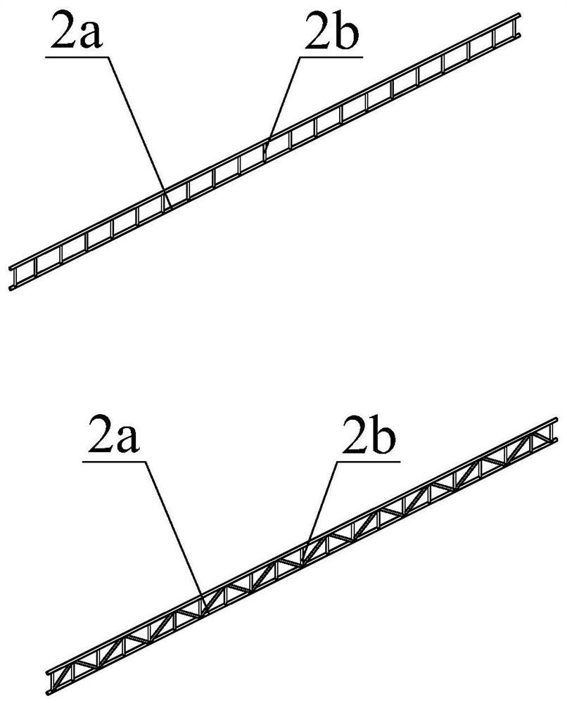
[0064] Such as Figure 3 ~ Figure 5 As shown, the steel bar truss 2 of this embodiment can adopt various structural forms.

[0065] First of all, for floors with low bearing performance requirements (such as the floor of the first floor), multiple straight steel bars can be directly configured as steel trusses.

[0066] Secondly, for middle and low-rise residential buildings, the load-carrying performance of the floor slabs has certain requirements, and reinforced structure steel trusses 2 can be used. Such as image 3 As shown, the steel truss 2 includes longitudinally arranged upper and lower chord main reinforcements 2a, and also includes web auxiliary reinforcements 2b ...


PUM


Abstract

The invention discloses a fabricated floor slab with a connecting component. The floor slab comprises a steel bar truss for bearing and a lightweight concrete slab, the steel bar truss is buried in the lightweight concrete slab to ensure that the lightweight concrete slab meets the bearing capacity of 200 kg or above per square meter, and the floor slab also comprises a connecting piece pre-buriedin the lightweight concrete slab and used for floor slab fabrication. On the premise that bearing performance is met, complete overall prefabrication of the floor slab is achieved, the manufactured floor slab is low in weight, high in strength and easy to fabricate, a steel structure frame does not need to be arranged in advance, the construction efficiency is greatly improved, and the construction cost is remarkably reduced.

Description

technical field [0001] The invention relates to the technical field of buildings, in particular to an assembled floor with connecting components. Background technique [0002] Prefabricated building refers to the transfer of a large number of on-site operations in the traditional construction method to the factory, where the building components and accessories (such as floor slabs, wall panels, stairs, balconies, etc.) are processed and manufactured in the factory, and transported to the construction site. Reliable connections are assembled and installed on site. Compared with traditional buildings, prefabricated buildings have the advantages of less on-site cast-in-place operations, a higher degree of standardization, shorter construction periods, more in line with the requirements of green buildings, and more energy-saving and environmentally friendly. In recent years, my country has attached great importance to the development of the prefabricated construction industry. ...

Claims


Application Information

Patent Timeline
Patent Type & Authority Applications(China)
IPC IPC(8): E04B5/02E04B5/10E04C5/06
CPCE04B5/02E04B5/023E04B5/10E04C5/0636
Inventor 罗克佐
Owner HUBEI SHENZHOU BUILDING MATERIAL
Learn More