An automatic discharge type continuous feeding device for wall decoration
A technology of automatic discharging and feeding device, which is applied in the direction of unloading device, mixer with rotating stirring device, transportation and packaging, etc. It can solve the problems of reducing the working speed, insufficient uniformity and affecting the quality of the wall, etc. Achieve the effects of improving work efficiency, reducing reclaiming time, and saving reclaiming time
- Summary
- Abstract
- Description
- Claims
- Application Information
AI Technical Summary
Problems solved by technology
Method used
Image
Examples
Embodiment 1
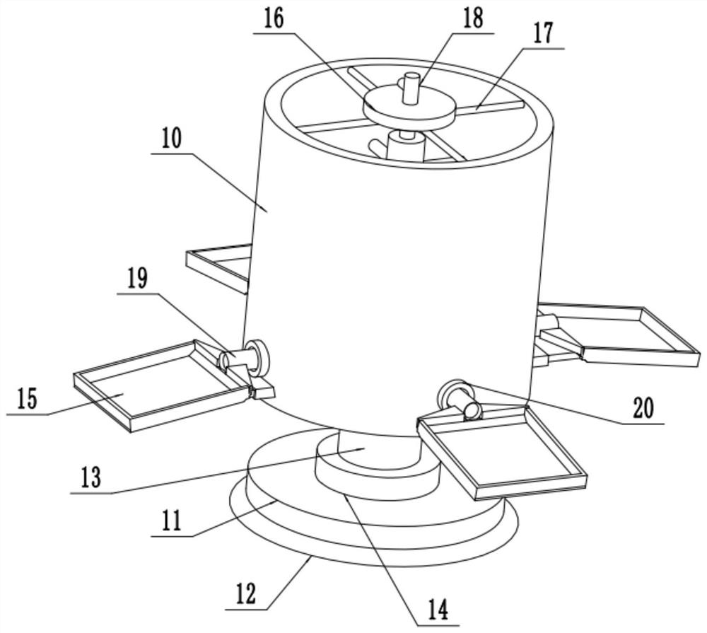
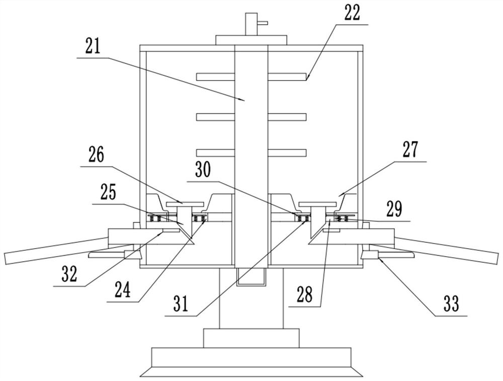
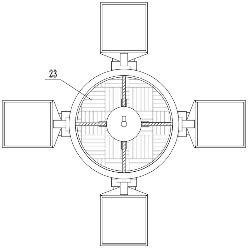
[0020] see Figure 1-3 , an automatic discharge type continuous feeding device for wall decoration, comprising a material barrel 10 and a base 11; the center of the bottom of the material barrel 10 is fixedly installed with a vertical rotating rod 13 downward, and the bottom of the rotating rod 13 is rotatably connected There is a base 11, by pushing the rotation of the rotating rod 13, it is convenient to adjust the use angle of the bucket 10, and the bottom of the base 11 is fixedly installed with a suction cup 12 for improving the stability of the base 11. The outer surface of the rotating rod 13 at the top of the base 11 is provided with an external thread and is threaded with a locking nut 14 for limiting the rotation of the rotating rod 13 . The center of the top of the barrel 10 is fixed on the support rod 17 fixed on the inner wall of the top of the barrel 10 through four groups of equally spaced ends, and a set of circular structure fixed blocks 16 are fixedly install...
Embodiment 2
[0024] On the basis of Embodiment 1, the center of the fixed block 16 is rotatably connected to a stirring shaft 21 whose vertical bottom end extends to the inner bottom of the material barrel 10, and the bottom end of the agitating shaft 21 is rotatably connected to the rotating shaft 21 through a bearing. The inner top of the rod 13 and the top of the stirring shaft 21 are fixedly connected upwards with a rotary handle 18 for promoting the rotation of the stirring shaft 21, and the outer surface of the stirring shaft 21 located inside the bucket 10 is fixedly installed with multiple groups from top to bottom. The stirring rod 22 is used to stir the liquid material inside the bucket 10 .
PUM
 Abstract
Description
Claims
Application Information
 - R&D
- Intellectual Property
- Life Sciences
- Materials
- Tech Scout
- Unparalleled Data Quality
- Higher Quality Content
- 60% Fewer Hallucinations
Browse by: Latest US Patents, China's latest patents, Technical Efficacy Thesaurus, Application Domain, Technology Topic, Popular Technical Reports.
© 2025 PatSnap. All rights reserved.Legal|Privacy policy|Modern Slavery Act Transparency Statement|Sitemap|About US| Contact US: help@patsnap.com


