Oil well induced flow system and induced flow process

An oil well and thin oil technology, applied in the field of oil well blowout induction system and blowout induction process, can solve problems such as temperature drop, incomplete blowout, and increase of wellhead back pressure, so as to reduce viscosity and density, avoid incomplete blowout, Guaranteed smooth progress

Pending Publication Date: 2020-12-11
PETROCHINA CO LTD
View PDF7 Cites 0 Cited by
  • Summary
  • Abstract
  • Description
  • Claims
  • Application Information

AI Technical Summary

Problems solved by technology

In the initial stage, since the temperature in the well is as high as 100°C and the pressure is as high as 10 MPa, the crude oil in the well can be released normally. A "dead oil" area is formed in the space, resulting in the phenomenon of stop spraying
Due to the shutdown of the oil well, the blowout will be incomplete. When the wellbore is opened for operation, the pressure in the well will be released during the operation, which will cause a blowout, which will cause incalculable losses to the environment, staff and oil production equipment.
In addition, at the end of the blowout period of the oil well, due to the low liquid production rate, low water content and lower temperature of the oil well, it is easy to cause freezing and plugging pipeline accidents in winter
[0004] At present, the method of replacing oil with clean water is used at the site to solve the problem of stopping the injection of "dead oil" in the wellbore. However, if the injection is not complete, the crude oil in the formation cannot be processed, and the energy accumulated in the formation will also be released. Problems causing blowouts have yet to come up with effective solutions

Method used


Image

  • Oil well induced flow system and induced flow process
  • Oil well induced flow system and induced flow process
  • Oil well induced flow system and induced flow process

Examples


Embodiment approach 1

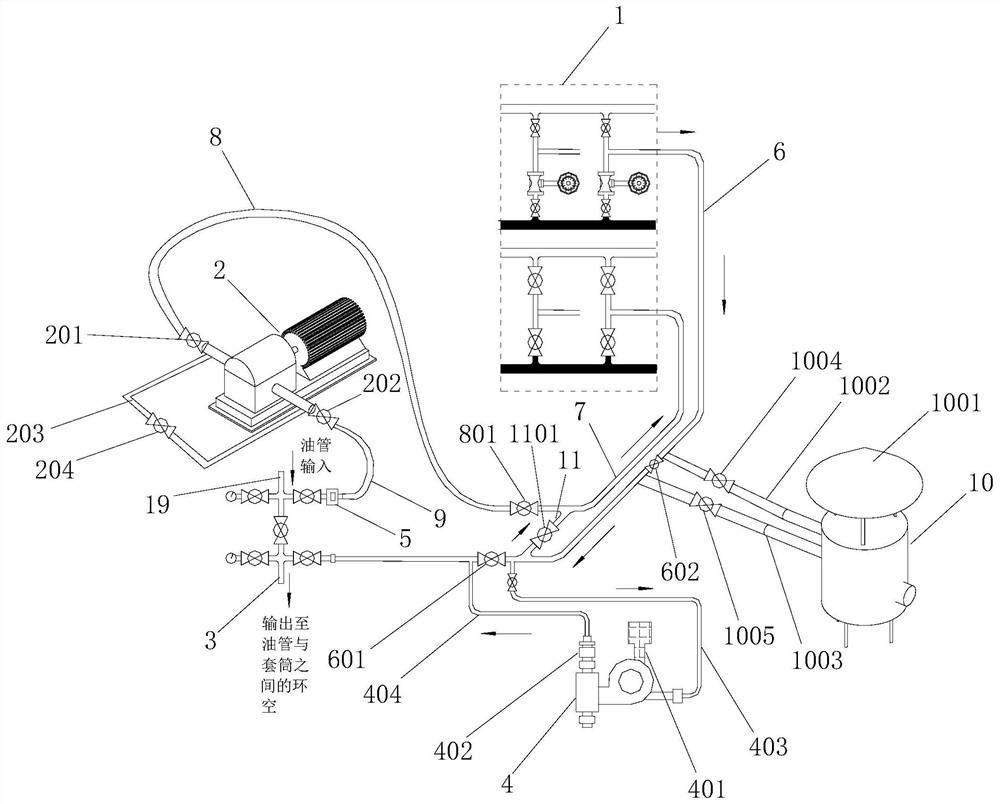
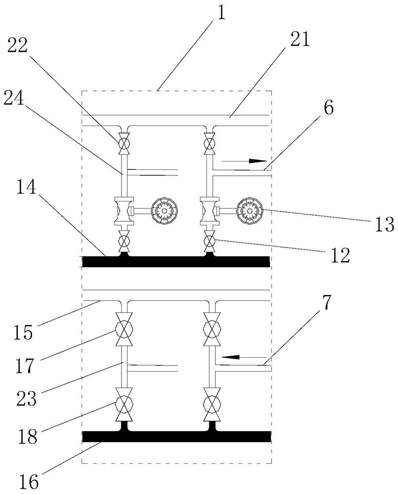
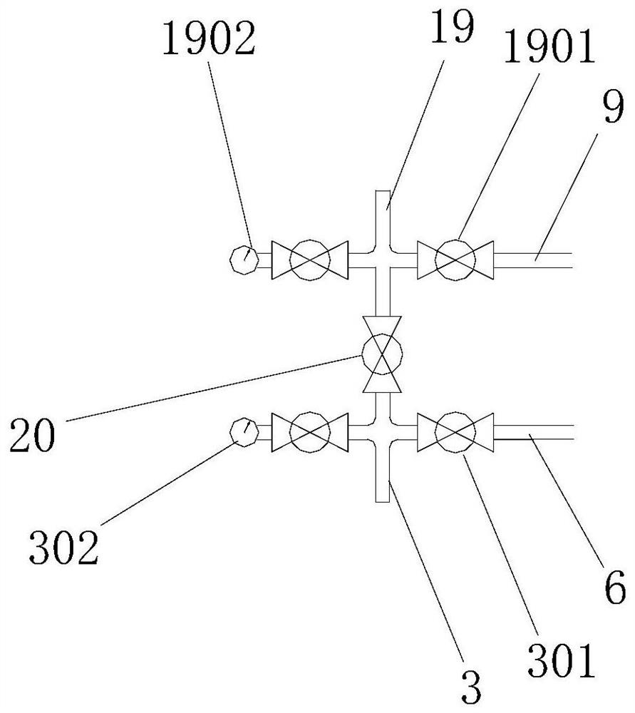
[0043] Such as Figure 1 to Figure 4 As shown, the present invention provides an oil well induced blowout system. The oil well induced blowout system includes a liquid control device 1, a pressurized liquid mixing device 4 and a negative pressure suction device 2. The liquid control device 1 is used to supply oil pipes and sleeves Input thin oil into the annular space between them and collect the return oil in the oil pipe. The pressurized liquid mixing device 4 is used to pressurize the thin oil in the annular space between the input oil pipe and the sleeve. The negative pressure suction device 2 Used to provide suction for return oil in the oil pipe. The liquid outlet of the liquid control device 1 is connected to one end of the oil mixing pipe 6, the other end of the oil mixing pipe 6 is connected to one end of the thin oil output pipe 3, and the other end of the thin oil output pipe 3 extends into the gap between the oil pipe and the sleeve. In the annular space, the pres...

Embodiment approach 2

[0066] Such as Figure 1 to Figure 4 As shown, the present invention provides a kind of oil well induced blowout technique, and this oil well induced blowout technique comprises the steps:

[0067] Step S1: Output the thin oil to the oil control mixing pipe 6 through the liquid outlet of the liquid control device 1, and transport the thin oil to the thin oil output pipe 3 through the oil mixing pipe 6; the oil mixing pipe 6 is provided with a wellhead furnace 10, and When the temperature of the thin oil in the oil pipe 6 is lower than the predetermined threshold, close the wellhead furnace connection valve 602 on the oil mixing pipe 6, open the wellhead furnace liquid inlet valve 1004 on the wellhead furnace liquid inlet pipe 1002 and the wellhead furnace outlet pipe 1003. The furnace outlet valve 1005 heats the thin oil in the oil mixing pipe 6 through the wellhead furnace 10 .

[0068] Step S2: Start the pressurized liquid mixing device 4 to pressurize the thin oil, press t...


PUM


Abstract

The invention discloses an oil well induced flow system and induced flow process. The oil well induced flow system comprises a liquid control device for inputting thin oil into an annulus between an oil pipe and a sleeve and collecting return oil in the oil pipe, a pressurizing liquid mixing device for pressurizing the thin oil input into the annulus, and a negative pressure suction device for providing suction force for the return oil in the oil pipe, wherein a liquid outlet of the liquid control device is connected with one end of an oil mixing pipe, the other end of the oil mixing pipe is connected with one end of a thin oil output pipe, the other end of the thin oil output pipe extends into the annulus, the pressurizing liquid mixing device is arranged on the thin oil output pipe, a liquid return port of the liquid control device is connected with one end of an oil return pipe, the other end of the oil return pipe is connected with a liquid outlet of the negative pressure suction device, a liquid inlet of the negative pressure suction device is connected with one end of an oil return inlet pipe, and the other end of the oil return inlet pipe extends into the oil pipe. The system and the process solve the technical problems that crude oil in an oil well is not blown out thoroughly, and blowout is caused when energy accumulated in a stratum is released.

Description

technical field [0001] The invention relates to the technical field of oil production engineering, in particular to an oil well induced blowout system and an induced blowout process. Background technique [0002] At present, the physical properties of crude oil in some oilfields in my country are ultra-heavy oil. For example, in the ultra-heavy oil area of ​​Liaohe Oilfield, the buried depth of oil wells is -650 to -920m, the effective thickness is 25.3m, the porosity is 30.8%, and the permeability 1660×10 -3 μm 2 , belonging to high porosity and high permeability reservoirs, the lithology is dominated by anisograined sandstone, followed by siltstone and conglomerate, with an average particle size of 0.425mm, and the cementation type is mainly pore cementation, and its ultra-heavy oil The average viscosity of crude oil is 16×104mpa s, and the density of crude oil is 1.0098g / cm 3 . [0003] For the crude oil production in this kind of super-heavy oil area, the development ...

Claims


Application Information

Patent Timeline
Patent Type & Authority Applications(China)
IPC IPC(8): E21B43/22E21B43/24E21B43/12F17D1/18
CPCE21B43/16E21B43/24E21B43/121F17D1/18
Inventor 饶德林柳转阳赵奇峰李燕敏李广龙韩兵许树琨林强姜宇鹏王军飞时梦临袁怡菲卞家忠王佳林尹淋淋张泉尚路野欧毅宋鹏张孝宁
Owner PETROCHINA CO LTD
Why Eureka
Try Eureka