Rotor engine and regulation and control method for operating parameters thereof

A rotor engine and rotor technology, which is applied in the direction of engine lubrication, engine components, combustion engines, etc., can solve the problems of small compression ratio, high engine fuel consumption, fuel type restrictions, etc., to improve the compression ratio, mix oil and gas evenly, and strengthen oil and gas mixed effect

Pending Publication Date: 2020-12-11
SHAANXI XIN NIAN POWER TECH GRP CO LTD
View PDF9 Cites 1 Cited by
  • Summary
  • Abstract
  • Description
  • Claims
  • Application Information

AI Technical Summary

Problems solved by technology

The rotary engine with this structure has high fuel consumption and low compression ratio, so it can only use the compression ignition combustion method, which has restrictions on the type of fuel

Method used


Image

  • Rotor engine and regulation and control method for operating parameters thereof
  • Rotor engine and regulation and control method for operating parameters thereof
  • Rotor engine and regulation and control method for operating parameters thereof

Examples


Embodiment 1

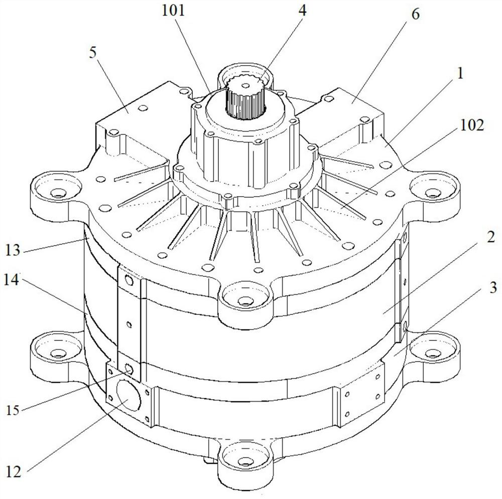
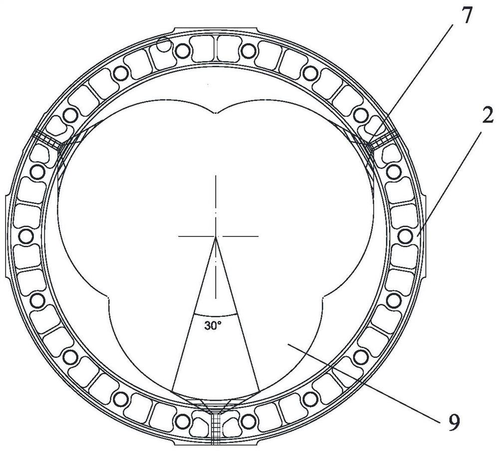
[0048] see figure 1 , a rotary engine, including a casing 3, and a rotor 8, the rotor 8 is located in the casing, the casing is assembled from multiple parts, including an upper end cover, an outer deflection cover 14, a stator 2, an inner The partial cover 13 and the lower end cover 1, the inside of the stator has a three-lobed cavity 9 surrounded by three sections of arc-shaped side walls (see figure 2 , 3 combustion chambers 7 are not connected to each other),

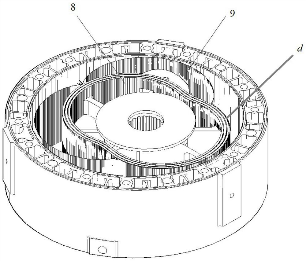
[0049] see image 3 and Figure 4 , the rotor is in the shape of "8" and is located in the three-lobed cavity 9 inside the stator. The arc of the head of the "8" is adapted to the arc forming the three-lobed cavity; Three symmetrically distributed combustion chambers 7 are arranged on the arc-shaped inner wall of the hollow cavity.

[0050] image 3 It shows the state when the head of the rotor is located in one of the three-lobe-shaped cavities. The head of the rotor 8 has an arc-shaped side wall. When the he...

Embodiment 2

[0060] This embodiment is a method for adjusting and controlling the operating parameters of the rotary engine based on the structure of the first embodiment and the operation method of the rotary engine of the first embodiment:

[0061] After assembling the rotary engine, inject lubricating oil from the lubricating oil hole until it is full. Lubricating oil circulates within the rotary engine to lubricate the rotors. In this operation embodiment, the fuel is diesel oil, and the coolant is engine oil. The rotary engine adopts compression ignition ignition, the compression ratio reaches more than 17, and the temperature can reach 600-700°C. During operation, the rotor rotates to fully mix the gas and oil in a swirling shape, so that the fuel can be fully burned.

[0062] With diesel as fuel, the displacement of the rotary engine is 2.5, and the speed is 3000-5000. The engine compression ratio is 22.3.

Embodiment 3

[0064] A rotary engine, comprising a housing, and a rotor 8, the rotor 8 is located in the housing,

[0065] The housing is assembled from multiple parts, including the upper end cover, the outer cover 14, the stator 2, the inner cover 13 and the lower end cover 1 connected in sequence. petal cavity 9,

[0066] The rotor is in the shape of "8" and is located in the three-lobed cavity inside the stator. The arc of the head of the "8" is adapted to the circular arc forming the three-lobed cavity; There are three symmetrically distributed combustion chambers on the arc-shaped inner wall of the cavity.

[0067] The component parameters of this embodiment are that the inner diameter of the main shaft installation hole 102 is 35 mm, and there is a tolerance of 0.01 mm with the main shaft. The opening of the combustion chamber is circular with a diameter of 60mm and a depth of 35mm. The radian of the opening of the combustion chamber is about 30 degrees, and the radian of the arc-...


PUM


Abstract

The invention provides a rotor engine and a regulation and control method for operating parameters thereof. The rotor engine comprises a housing and a rotor. The rotor is located in the housing, and the housing is formed by assembling multiple parts and comprises an upper end cover, an outer partial cover, a stator, an inner partial cover and a lower end cover that are connected in sequence. The stator is internally provided with a trivalvular cavity encircled by three arc-shaped side walls, the rotor which is "8"-shaped is located in the trivalvular cavity in the stator, and an arc of a headof "8" is matched with a circular arc of the trivalvular cavity; The trivalvular cavity is provided with an arc-shaped inner wall, and three symmetrically distributed combustion chambers are arrangedon the arc-shaped inner wall of the trivalvular cavity. Based on intensive study on the rotor engine, the separation distance between the arc-shaped side wall of the rotor and the arc-shaped inner wall of the trivalvular cavity is further adjusted, so that an engine pressure ratio is further improved.

Description

technical field [0001] The invention belongs to the technical field of engines, and in particular relates to a rotary engine and a method for regulating and controlling its operating parameters. Background technique [0002] The rotary engine uses the rotary motion of the rotor in the cylinder to control compression and discharge, which is different from the traditional reciprocating piston engine, which changes the linear reciprocating motion into rotary motion. Compared with the reciprocating engine, the rotary engine cancels the useless linear motion, so the rotary engine with the same power is smaller in size, lighter in weight, and has lower vibration and noise. It has become a novel and efficient engine technology in the automotive industry. The more representative rotor engine technology is the triangular rotor engine of Mazda Corporation, such as the rotor piston engine and its design method disclosed in the publication number CN101413436. The offset eccentric shaft...

Claims


Application Information

Patent Timeline
Patent Type & Authority Applications(China)
IPC IPC(8): F02B53/00F02B55/08F02B55/02F02B55/14F02B53/08F02B53/04F02B55/10F02B53/02F01M11/00
CPCF02B53/00F02B55/08F02B55/02F02B55/14F02B53/08F02B53/04F02B55/10F02B53/02F01M11/00Y02T10/12
Inventor 赵新年李军生计超
Owner SHAANXI XIN NIAN POWER TECH GRP CO LTD
Why Eureka
Try Eureka