
Hydraulic system capable of throwing snow

A technology of hydraulic system and hydraulic pump, applied in the field of hydraulic system, can solve the problems of large hydraulic shock, large efficiency loss, and inability to set the flow rate of the snow blower, and achieve the effects of reducing power loss, eliminating pressure shock and avoiding sudden stop

Pending Publication Date: 2020-12-11
XCMG CONSTR MACHINERY
View PDF0 Cites 0 Cited by
  • Summary
  • Abstract
  • Description
  • Claims
  • Application Information

AI Technical Summary

Problems solved by technology

[0002] At present, loaders, skid steer loaders, backhoe loaders and other engineering machinery at home and abroad are equipped with a variety of tools to meet different working conditions; among them, snow blowers are one of the more common tools, mostly used in cold regions Snow removal equipment in winter, but currently the snow blower is generally controlled by a common valve block. When working, part of the pump flow is used for the work of the snow blower, and the excess flow flows back to the oil tank through the overflow valve, which cannot be controlled by the flow required by the snow blower. Set the flow rate, the efficiency loss is large, and the hydraulic shock is large

Method used


Image

  • Hydraulic system capable of throwing snow

Examples


Embodiment Construction

[0023] The present invention will be further described below in conjunction with the accompanying drawings. The following examples are only used to illustrate the technical solution of the present invention more clearly, but not to limit the protection scope of the present invention.

[0024] In describing the present invention, it should be understood that the terms "center", "longitudinal", "transverse", "upper", "lower", "front", "rear", "left", "right", " The orientations or positional relationships indicated by "vertical", "horizontal", "top", "bottom", "inner" and "outer" are based on the orientations or positional relationships shown in the drawings, and are only for the convenience of describing the present invention and Simplified descriptions, rather than indicating or implying that the device or element referred to must have a particular orientation, be constructed and operate in a particular orientation, and thus should not be construed as limiting the invention. ...


PUM


Abstract

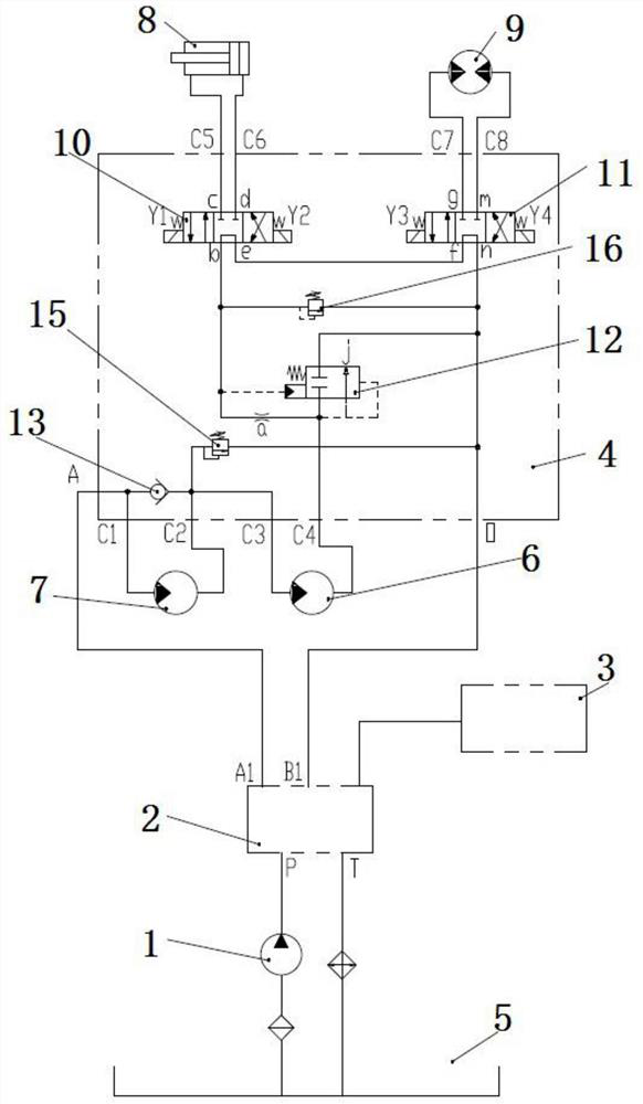
The invention discloses a hydraulic system capable of throwing snow, and belongs to the technical field of engineering machinery. The hydraulic system comprises a snow throwing assembly, a hydraulic pump, a multi-way valve, an operation assembly, a control assembly and a hydraulic oil tank, the hydraulic oil tank is connected with the multi-way valve, the multi-way valve is connected with the operation assembly, the multi-way valve is connected with the snow throwing assembly through the control assembly, and the snow throwing assembly comprises an auger motor, a fan motor, an angle adjustingoil cylinder and a steering motor, the hydraulic pump is connected with the control assembly through the multi-way valve, the multi-way valve is connected with the operation assembly, the multi-way valve is connected with the hydraulic oil tank, and the auger motor, the fan motor, the angle adjusting oil cylinder and the steering motor are all connected with the control assembly. According to thehydraulic system capable of throwing snow, the snow throwing operation is controlled by arranging an independent snow throwing control assembly, the snow throwing operation is conducted according to needs, the loss of hydraulic efficiency is reduced, and impact on the hydraulic system is avoided.

Description

technical field [0001] The invention relates to a hydraulic system capable of throwing snow, belonging to the technical field of engineering machinery. Background technique [0002] At present, loaders, skid steer loaders, backhoe loaders and other engineering machinery at home and abroad are equipped with a variety of tools to meet different working conditions; among them, snow blowers are one of the more common tools, mostly used in cold regions Snow removal equipment in winter, but currently the snow blower is generally controlled by a common valve block. When working, part of the pump flow is used for the work of the snow blower, and the excess flow flows back to the oil tank through the overflow valve, which cannot be controlled by the flow required by the snow blower. If the flow rate is set, the efficiency loss is large, and the hydraulic shock is large. Contents of the invention [0003] The purpose of the present invention is to overcome the deficiencies in the p...

Claims


Application Information

Patent Timeline
IPC IPC(8): F15B13/02E01H5/07
CPCE01H5/076F15B13/02F15B13/027
Inventor 杨娟谢朝阳朱右东刘亚
Owner XCMG CONSTR MACHINERY
Learn More