Steel backing structure for preventing brake pad from falling off, steel backing manufacturing die and production process

A technology of brake pads and molds, which is applied in the field of brake pads to achieve the effects of performance improvement, safety accident reduction, and high performance requirements

Pending Publication Date: 2020-12-11
烟台兴创汽车配件有限公司
View PDF0 Cites 2 Cited by
  • Summary
  • Abstract
  • Description
  • Claims
  • Application Information

AI Technical Summary

Problems solved by technology

[0006] Aiming at the problems in the prior art, the steel back structure for preventing the brake pads from falling off, the steel back manufacturing mold and the production process provided by the present invention can solve the requirements of the existing large automobiles for the light weight and high performance of the brake pads, and at the same time, the friction material will not detached from the steel back

Method used


Image

  • Steel backing structure for preventing brake pad from falling off, steel backing manufacturing die and production process
  • Steel backing structure for preventing brake pad from falling off, steel backing manufacturing die and production process
  • Steel backing structure for preventing brake pad from falling off, steel backing manufacturing die and production process

Examples


Embodiment 1

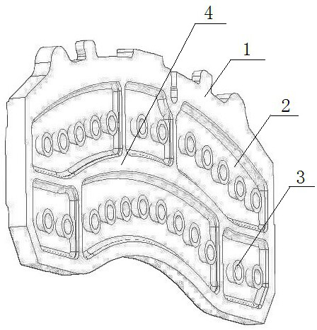
[0037] In this embodiment, a steel back structure is provided to prevent the brake pads from falling off. The size and shape of the present invention are for the convenience of describing the steel back structure, and the present invention is not limited to this embodiment.

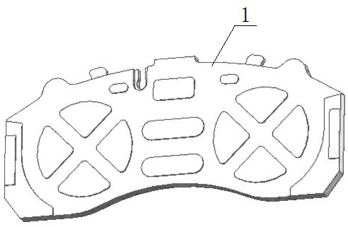
[0038] The structure of the body of the steel back is double-sided, one side is a plane, which is called the front in this application, and the other side is the side where the steel back contacts the friction material, which is called the back in this application. The convex-shaped structure, and the peripheral dimension of the top of the convex-shaped structure is larger than the peripheral dimension of the bottom, the upper surface of the convex-shaped structure is an arc surface concave inward, and the outer contour of the upper surface of the convex-shaped structure is circular, square or polygon, the side can be any shape, but it is necessary to ensure that the raised structure has a large head and a...

Embodiment 2

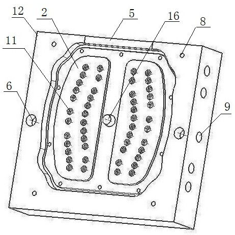
[0041] In this embodiment, the mold is used to make the steel back structure. The mold is divided into two sets, one set is mold one and mold two for producing the friction surface, and the other set is mold three and mold four for producing the back surface. In this embodiment Take the simultaneous production of two steel backs as an introduction.

[0042] Based on the steel back structure of Example 1, mold 1 and mold 2 for producing the friction surface are used together.

[0043] Such as image 3 As shown, there are reverse draft convex nails on the production friction surface. For the convenience of explanation, the orientation terms such as left, right, front, back, and upper surface are used. This application is not limited to this, corresponding to two steel backs and two concave surfaces. The regions are arranged symmetrically on the upper surface of mold one, separated by pouring columns in the middle, and the size, shape, and structure of the two concave regions on...

Embodiment 3

[0052] In this embodiment, the manufacturing process of the steel back structure to prevent the brake pads from falling off, after the mold is developed, it needs to be installed on the core shooter, and then heated to 200-240°C through the heating tube, and the temperature is measured by the thermocouple installed on the mold. The equipment automatically monitors the temperature rise and fall. Afterwards, adjust the sand shooting pressure of the equipment to 3.5-4MPa, and the sand shooting time to 2-4s, and shoot the coated sand into the cavity of the mold through the sand shooting port. Curing 60-90s. Remove the shell and let it cool on a flat plate for 4-5 hours. It is necessary to spray a release agent in the mold cavity every time the shell is made. After production, it is necessary to assemble the core of the inverted tapered convex nail on the back into the sand shell of the front structure. Then assemble the sand shell to 25-30 layers, clamp and install the sprue cu...


PUM


Abstract

The invention belongs to the field of brake pads, and particularly relates to a steel backing structure for preventing a brake pad from falling off, a steel backing manufacturing die and a productionprocess. A concave surface area is formed in the side face, making contact with a friction material, of a steel backing, a plurality of reverse drawing die protruding nails integrally formed with a steel backing body are arranged in the concave surface area, the reverse drawing die protruding nails are each of a structure with the top end peripheral size being larger than the bottom end peripheralsize, and the upper surface of each protruding structure is an inwards-concave arc surface; and meanwhile a complete set of dies are manufactured for steel backing production. The requirements of anexisting large automobile for the light weight and high performance of the brake pad are met, and meanwhile the friction material cannot fall off from the steel backing.

Description

technical field [0001] The invention belongs to the field of brake pads, and in particular relates to a steel back structure for preventing brake pads from falling off, a steel back manufacturing mold and a production process. Background technique [0002] The brake pad includes steel back, friction material and other main parts and other auxiliary parts, that is, the steel back is a part of the brake pad. The purpose of the steel back is mainly to fix the friction material, which is easy to install on the brake system. The steel back mainly plays a fixed role, which is manifested in manufacturing: the powdery friction material (mostly) undergoes chemical and physical effects under high temperature and high pressure, and is pressed onto the steel back to form a solid (also formed separately and then riveted), some of which are A cushion will be added between the steel back and the friction material. This part does not play a friction role, but is mainly used for noise reduc...

Claims


Application Information

Patent Timeline
Patent Type & Authority Applications(China)
IPC IPC(8): F16D69/04B22C9/22B22C9/02
CPCB22C9/02B22C9/22F16D69/0408F16D2069/045F16D2250/0007
Inventor 冯兴平袁凯绪杜坡
Owner 烟台兴创汽车配件有限公司
Why Eureka
Try Eureka