
Tracking error estimation method for servo drive shaft

A technology of servo drive and tracking error, which is applied in the testing of mechanical components, testing of machine/structural components, measuring devices, etc., can solve problems such as difficult operation, low efficiency, and failure to promote, and achieve overcoming operational difficulties, fast and Accurately Estimated Effects

Active Publication Date: 2020-12-11
TSINGHUA UNIV
View PDF9 Cites 0 Cited by
  • Summary
  • Abstract
  • Description
  • Claims
  • Application Information

AI Technical Summary

Problems solved by technology

The servo drive shaft is a complex mechatronic system, and it is difficult to effectively estimate its tracking error
Traditional methods often require the establishment of complex models and simulations with the help of industrial software. Although the estimation results of the tracking error of the servo drive shaft can be obtained, the operation is difficult and inefficient, and it cannot be quickly promoted in the industrial field.

Method used


Image

  • Tracking error estimation method for servo drive shaft
  • Tracking error estimation method for servo drive shaft
  • Tracking error estimation method for servo drive shaft

Examples


Embodiment Construction

[0025] The present invention will be described in further detail below in conjunction with the accompanying drawings and specific embodiments.

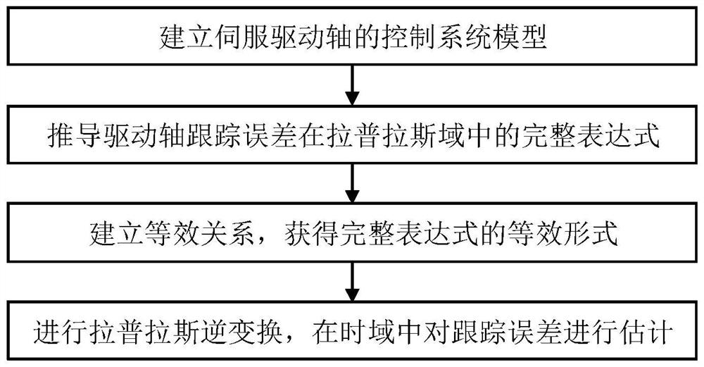
[0026] figure 1 Shown is a flow chart of a tracking error estimation method for a servo drive shaft of the present invention. In order to understand the present invention more clearly, a CNC machine tool servo drive shaft control system is taken as an example for illustration.

[0027] see figure 2 ,according to figure 2 The block diagram of the CNC machine tool servo drive shaft control system is shown, and the control system model of the servo drive shaft is established as follows:

[0028]

[0029] In the formula, G pc , G vc with G p are respectively the position loop controller, the speed loop controller and the control object of the servo drive shaft, K pp is the proportional gain of the position loop controller, K pv with T v are the proportional gain and integral time constant of the speed loop controller respecti...


PUM


Abstract

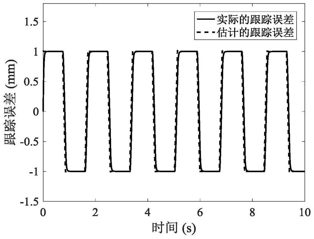
The invention discloses a tracking error estimation method for a servo drive shaft, and belongs to the technical field of mechatronics. The method comprises the following steps: firstly, establishinga control system model of the servo drive shaft, and deriving a complete expression of a tracking error in a Laplace domain; further obtaining an equivalent form of a complete expression according tocomponent characteristics of a displacement instruction signal; and finally, estimating the tracking error of the servo drive shaft in the time domain through Laplace inverse transformation. By utilizing the method provided by the invention, rapid and accurate estimation of the tracking error of the servo drive shaft is realized in the time domain, problems of difficult operation and low efficiency of the traditional method are overcome, and an accurate and convenient tool is provided for field engineering technicians.

Description

technical field [0001] The invention belongs to the technical field of mechatronics, and in particular relates to the tracking error estimation problem of a servo drive shaft. Background technique [0002] Servo drive shafts include linear feed shafts and rotary shafts, which are the basic components of advanced manufacturing equipment represented by CNC machine tools. They are used to achieve high-precision motion and are widely used in industrial fields. Tracking error is one of the core indicators to evaluate the performance of servo drive shaft, and it is of great significance to carry out research on tracking error. [0003] In the actual application process of the servo drive shaft, engineers and technicians need to effectively estimate its tracking error to judge the working state of the servo drive shaft and formulate corresponding performance improvement plans. The servo drive shaft is a complex mechatronic system, and it is difficult to effectively estimate its tr...

Claims


Application Information

Patent Timeline
Patent Type & Authority Applications(China)
IPC IPC(8): G01M13/00
CPCG01M13/00
Inventor 王冬王立平
Owner TSINGHUA UNIV
Learn More