Folding optical fiber laser emitting device

A fiber laser and launching device technology, applied in optics, optical components, instruments, etc., can solve the problems of unfavorable aiming, long length of fiber laser launching device, insufficient laser power density, etc., to increase the divergence angle, easy to carry and use, The effect of increasing the laser power density

Pending Publication Date: 2020-12-11
湖南兵器光电科技有限公司
View PDF0 Cites 0 Cited by
  • Summary
  • Abstract
  • Description
  • Claims
  • Application Information

AI Technical Summary

Problems solved by technology

[0004] One of the problems existing in the current laser EOD devices is that the laser power density to the target is not enough, and the length of the fiber laser emitting device is too long, which is not conducive to transportation, placement and on-site installation. In addition, the lasers of the existing laser emitting de

Method used


Image

  • Folding optical fiber laser emitting device
  • Folding optical fiber laser emitting device
  • Folding optical fiber laser emitting device

Examples


Embodiment Construction

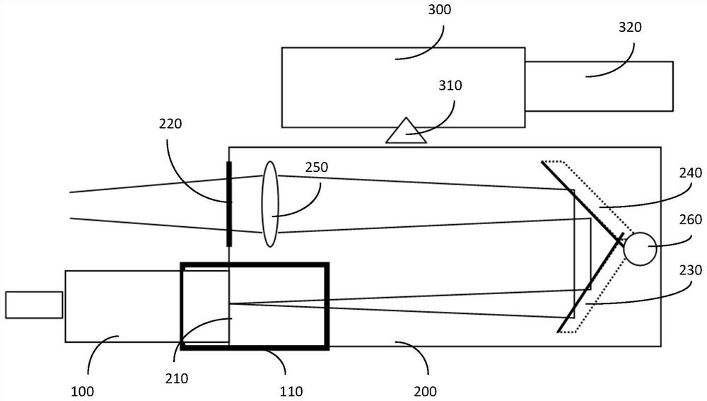
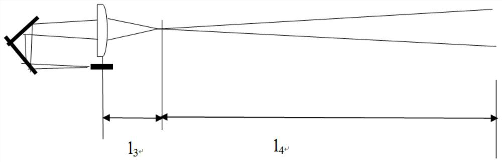
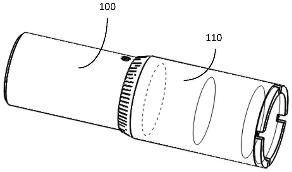
[0023] Embodiments of the present invention are described in detail below, examples of which are shown in the drawings, wherein the same or similar reference numerals designate the same or similar elements or elements having the same or similar functions throughout. The embodiments described below by referring to the figures are exemplary only for explaining the present invention and should not be construed as limiting the present invention.

[0024] In the description of the invention, it should be understood that the orientation descriptions, such as up, down, front, back, left, right, etc. indicated orientations or positional relationships are based on the orientations or positional relationships shown in the drawings, and are only for the purpose of It is convenient to describe the present invention and simplify the description, but does not indicate or imply that the device or element referred to must have a specific orientation, be constructed and operate in a specific or...


PUM


Abstract

The invention discloses a folding optical fiber laser emitting device which comprises a QBH optical fiber head, a folding reflection box and a sighting telescope installed at the top of the box body.The QBH optical fiber head is used for emitting laser, a light inlet and a light outlet which are vertically parallel are formed in one face of the light path reflection box, and the QBH optical fiberhead is installed on the light inlet. The incident surface of a first reflector faces the laser emitting end of the QBH optical fiber head, the reflecting surface of the first reflector faces the incident surface of a second reflector, the reflecting surface of the second reflector faces the light outlet, and a focusing lens is located between the second reflector and the light outlet. A foldingstructure is adopted to increase the focal length of the lens and effectively compress the divergence angle of an emergent Gaussian beam, so that the target laser power density is improved; and meanwhile, the length of the folding reflection box is reduced due to the design of the folding light path, and carrying and using are convenient. The problem that the QBH optical fiber head affects aimingof an operator is solved, and the operator can approach the eyepiece of the optical sighting telescope with eyes for aiming without hindrance.

Description

technical field [0001] The invention relates to the field of laser anti-explosion devices, in particular to a folding optical fiber laser emitting device. Background technique [0002] The main principle of laser detonation is to irradiate the high-energy laser beam generated by the fiber laser to the detonation target (such as a mine). On the one hand, the laser beam interacts with the surface shell of the detonation target, ablates or disintegrates its shell; On the one hand, the heat absorbed and conducted by the shell heats the internal explosive of the EOD target, causing the temperature rise, thermal decomposition, deflagration and even detonation of the explosive, etc. The two aspects interweave and eventually cause the EOD target to fail. [0003] As a long-distance non-contact detonation method, the advantages of laser detonation compared with the traditional detonation method are as follows: 1. The working distance of laser detonation is relatively long, and the de...

Claims


Application Information

Patent Timeline
IPC IPC(8): G02B17/06G02B27/09F42D5/04
CPCF42D5/04G02B17/0673G02B27/0977
Inventor 李文煜邹清波蒋武刘彬汪愈均
Owner 湖南兵器光电科技有限公司
Why Eureka
Try Eureka