Rural power grid distribution transformer

A technology for distribution transformers and rural power grids, applied in the field of transformers, can solve problems such as corrosion of heat dissipation panels, rust and damage of heat dissipation panels, and affecting heat dissipation of transformers, and achieve the effect of accelerating emissions

Inactive Publication Date: 2020-12-11
广州优讯环保科技有限公司
View PDF7 Cites 3 Cited by
  • Summary
  • Abstract
  • Description
  • Claims
  • Application Information

AI Technical Summary

Problems solved by technology

[0003] At present, there is an existing distribution transformer for rural power grids. In order to avoid harm to people’s lives, the transformer is usually installed in an outdoor location in a remote corner with relatively little traffic. The heat dissipation panel on the surface of the transformer is convenient for heat dissipa...

Method used


Image

  • Rural power grid distribution transformer
  • Rural power grid distribution transformer
  • Rural power grid distribution transformer

Examples


Embodiment 1

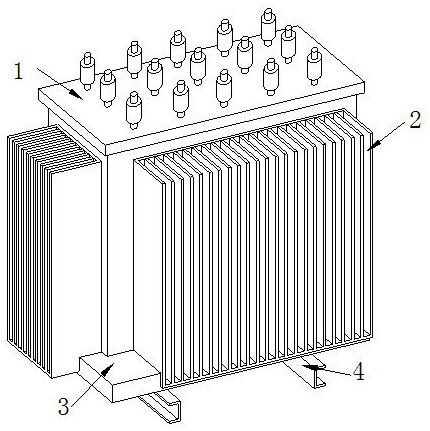
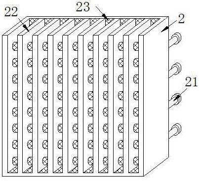
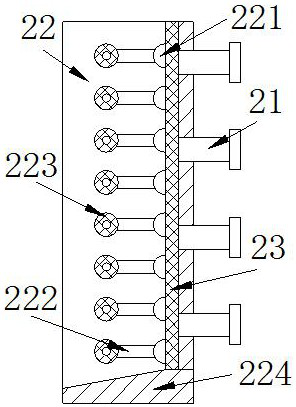
[0029] The present invention provides a distribution transformer for rural power grid, the structure of which includes a chassis 1, a heat dissipation panel 2, a bottom plate 3, and a mounting rod 4. The bottom of the chassis 1 is connected to the upper surface of the bottom plate 3 by welding, and the heat dissipation panel 2 is embedded in the On the outer surface of the chassis 1, the bottom of the bottom plate 3 is connected to the installation rod 4 by bolts, the heat dissipation panel 2 includes a connecting rod 21, a heat sink 22, and a positioning block 23, and the connecting rod 21 is connected to the back of the heat dissipation panel 2 by welding, The heat sink 22 is embedded in the heat dissipation panel 2, the positioning block 23 is close to the inner wall of the heat dissipation panel 2 and welded to the back of the heat dissipation fin 22, the distance between each heat sink 22 is equal, and the connecting rod 21 has four rows, which is beneficial to fix the hea...

Embodiment 2

[0035] The present invention provides a distribution transformer for rural power grid, the structure of which includes a chassis 1, a heat dissipation panel 2, a bottom plate 3, and a mounting rod 4. The bottom of the chassis 1 is connected to the upper surface of the bottom plate 3 by welding, and the heat dissipation panel 2 is embedded in the On the outer surface of the chassis 1, the bottom of the bottom plate 3 is connected to the installation rod 4 by bolts, the heat dissipation panel 2 includes a connecting rod 21, a heat sink 22, and a positioning block 23, and the connecting rod 21 is connected to the back of the heat dissipation panel 2 by welding, The heat sink 22 is embedded in the heat dissipation panel 2, the positioning block 23 is close to the inner wall of the heat dissipation panel 2 and welded to the back of the heat dissipation fin 22, the distance between each heat sink 22 is equal, and the connecting rod 21 has four rows, which is beneficial to fix the hea...


PUM


Abstract

The invention discloses a rural power grid distribution transformer. The rural power grid distribution transformer structurally comprises a case, a heat dissipation panel, a bottom plate and an installation rod, the bottom of the case is connected to the upper surface of the bottom plate in a welded mode, the heat dissipation panel is fixedly embedded in the outer surface of the case, and the bottom of the bottom plate is connected with the installation rod through bolts. The transformer has the beneficial effects that swing blocks in through holes in positioning rods temporarily store fallingrainwater, the positioning rods and a cooling fin are driven by the gravity of the rainwater to move downwards, the rainwater can flow downwards conveniently, the situation that the cooling fin rustdue to the fact that the rainwater remains on the cooling fin is avoided, a drainage plate is stressed to move downwards along with a supporting plate in the pressing process of the cooling fin, the drainage plate shakes up and down under the elastic force of the rubber spring, the cooling fin shakes up and down to shake rainwater down to the surface of the drainage plate, meanwhile, an air bag isextruded to blow air into a through pipe, and the air is blown into the air blowing hole to enable a baffle to be opened to blow the rainwater on the drainage plate, so rainwater drainage is accelerated, and rusting of the heat dissipation panel caused by rainwater remaining in the heat dissipation panel is avoided.

Description

technical field [0001] The invention relates to the field of transformers, in particular to a rural power distribution transformer. Background technique [0002] Distribution transformer refers to a kind of electrical equipment used to transform AC voltage and current in the power distribution system to transmit AC power. For the safe installation of distribution transformers, it is usually installed on the pole or in the open. Transformers enable every household to use stable voltage and current. [0003] At present, there is an existing distribution transformer for rural power grids. In order to avoid harm to people’s lives, the transformer is usually installed in an outdoor location in a remote corner with relatively little traffic. The heat dissipation panel on the surface of the transformer is convenient for heat dissipation of the transformer. In the seasons of alternating sunny and rainy seasons, raindrops remain on the heat dissipation panel, causing the rainwater t...

Claims


Application Information

Patent Timeline
IPC IPC(8): H01F27/02H01F27/08H01F27/23
CPCH01F27/025H01F27/08H01F27/23
Inventor 卢敏
Owner 广州优讯环保科技有限公司
Why Eureka
Try Eureka