
Transformer magnetic core feeding device of power adapter

A technology for power adapters and transformers, which is applied in the manufacture of inductors/transformers/magnets, magnetic cores, and circuits. Force area, effect of clamping stability

Inactive Publication Date: 2020-12-11
卢伟忠
View PDF10 Cites 0 Cited by
  • Summary
  • Abstract
  • Description
  • Claims
  • Application Information

AI Technical Summary

Problems solved by technology

However, when the existing magnetic core feeding equipment is feeding, the existing technology adopts double-sided clamping for the clamping and fixing of the magnetic core. Although it can be properly adjusted according to the diameter of the magnetic core, due to the The shape of the magnetic core is different for different signals. The magnetic cores include ring magnetic core, EP type magnetic core, PQ type magnetic core, EC, ETD and EER type magnetic core, etc., especially EC, ETD and EER type Magnetic core, this type of magnetic core is between the E type and the pot type, the central column is cylindrical, and the two sides are hollowed out. In the clamping on both sides, the splint is easily located in the hollowed out position, and the diameter of the central column is smaller than the arc The clamping diameter of the plywood is not sufficient, which is prone to the phenomenon of empty clamping, and then when feeding, there will be material leakage or falling.

Method used


Image

  • Transformer magnetic core feeding device of power adapter
  • Transformer magnetic core feeding device of power adapter
  • Transformer magnetic core feeding device of power adapter

Examples


Embodiment 1

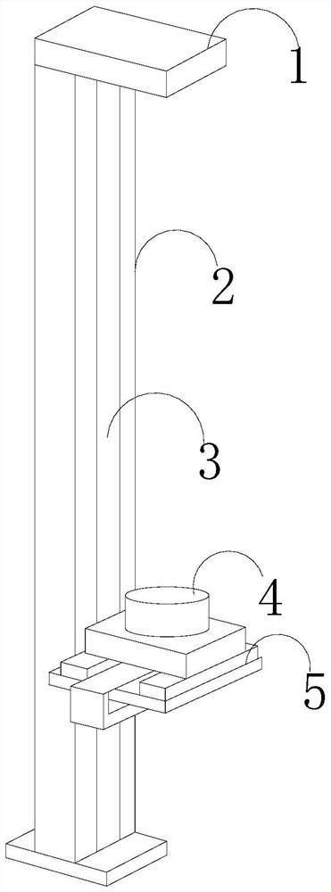
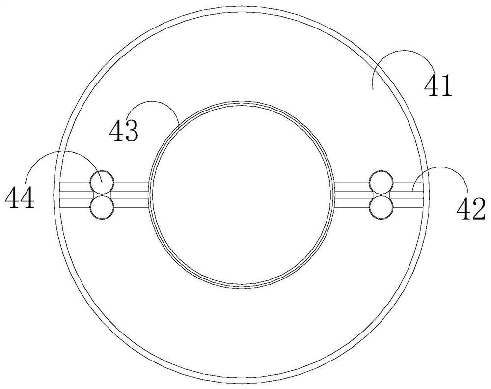
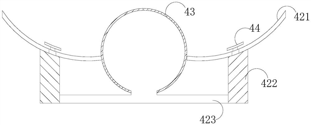
[0027] Such as Figure 1-Figure 6 As shown, the present invention provides a transformer magnetic core feeding device for a power adapter. The upper top plate 1 is fixed, the lifting screw 3 is installed on the supporting column 2, the lifting screw 3 is movably matched with the lifting base 5, and the lifting base 5 is provided with a clamping cavity 4, and the clamping cavity The inside of 4 is composed of a cavity 41, a sliding adjustment mechanism 42, an extruding air bag 43, and a clamping assembly 44. The cavity 41 is provided with a sliding adjustment mechanism 42 and an extruding air bag 43, and the extruding air bag 43 Cooperating with the clamping assembly 44, the sliding adjustment mechanism 42 is movably fitted with the clamping assembly 41. The sliding adjustment mechanism 42 includes an arc-shaped slide rail 421, a telescopic support shaft 422, and a connecting pipe 423. The arc-shaped The clamping assembly 44 is connected to the slide rail 421, and the telescop...


PUM


Abstract

The invention discloses a transformer magnetic core feeding device of a power adapter. The device structurally comprises an upper top plate, a supporting column, a lifting lead screw, a material clamping cavity and a lifting base, the upper top plate is fixed to the top end of the supporting column, the lifting lead screw is installed on the supporting column, the lifting lead screw is movably matched with the lifting base, the material clamping cavity is formed in the lifting base, a cavity, a sliding direction adjusting mechanism, an extrusion air bag and a clamping assembly are formed in the material clamping cavity, the sliding direction adjusting mechanism and the extrusion air bag are arranged in the cavity, the extrusion air bag is matched with the clamping assembly, and the clamping assembly is movably matched with the sliding direction adjusting mechanism. The extrusion air bag is matched with the clamping assembly, and the extrusion air bag and the clamping assembly are bothlocated at the bottom of the material clamping cavity, so when a workpiece is placed, only a solid face needs to be directly placed at the bottom of the material clamping cavity, a clamping sucker canbe used for directly adsorbing and fixing the workpiece, the empty clamping phenomenon cannot occur, and the situation of falling or material leakage cannot occur in the feeding process.

Description

technical field [0001] The invention relates to an electronic component processing machine, in particular to a transformer magnetic core feeding device for a power adapter. Background technique [0002] With the continuous development of electronic technology, various electronic products appear in people's lives, and most of these electronic products need to use transformers. However, when the existing magnetic core feeding equipment is feeding, the existing technology adopts double-sided clamping for the clamping and fixing of the magnetic core. Although it can be properly adjusted according to the diameter of the magnetic core, due to the The shape of the magnetic core is different for different signals. The magnetic cores include ring magnetic core, EP type magnetic core, PQ type magnetic core, EC, ETD and EER type magnetic core, etc., especially EC, ETD and EER type Magnetic core, this type of magnetic core is between the E type and the pot type, the central column is c...

Claims


Application Information

Patent Timeline
Patent Type & Authority Applications(China)
IPC IPC(8): H01F41/02
CPCH01F41/0206
Inventor 卢伟忠
Owner 卢伟忠
Learn More