Preparation process of permanent magnet alloy material
A technology of alloy material and preparation process, which is applied to magnets, magnetic objects, permanent magnets, etc., can solve the problem of no polishing process in the process, and achieve the effect of flexible positioning, fast placement, and improved polishing efficiency.
- Summary
- Abstract
- Description
- Claims
- Application Information
AI Technical Summary
Problems solved by technology
Method used
Image
Examples
specific Embodiment approach 1
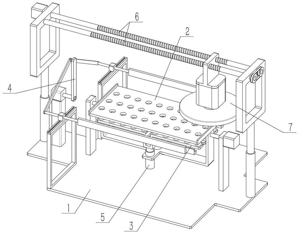
[0037] As shown in the figure, a preparation process of a permanent magnet alloy material, the process includes the following steps:
[0038] Step 1, the middle part of the permanent magnet alloy shaped as a square cylinder is punched to obtain the initial material;
[0039] Step 2, placing the holes on the multiple raw materials upwards and placing them in a row in the permanent magnet alloy material preparation device;
[0040] Step 3, polishing the upper end faces of multiple primary materials;
[0041] Step 4, polishing the front and rear end faces of multiple primary materials;
[0042] Step 5, polishing the lower end surfaces of the plurality of primary materials;
[0043] Step 6, polishing the left and right end faces of multiple primary materials to obtain finished materials;
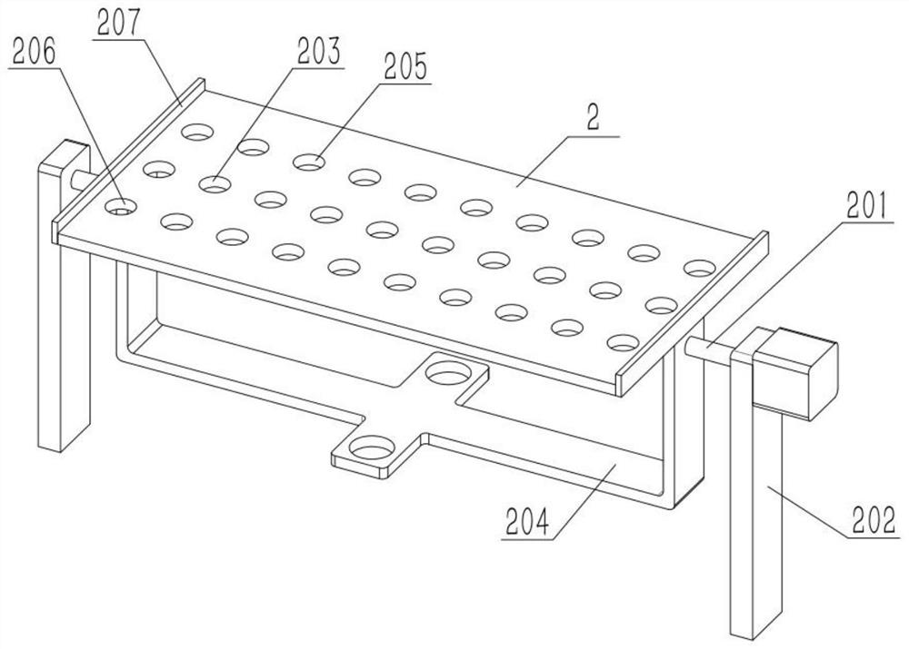
[0044]The preparation process of the above permanent magnet alloy material also includes a preparation device for the permanent magnet alloy material; the device for the permanent magnet allo...
specific Embodiment approach 2
[0046] As shown in the figure, the preparation device of the permanent magnet alloy material also includes a frame 303 and a clamping plate I 304. The front and rear ends of the push table 3 are respectively fixed with a frame 303, and the outer ends of each frame 303 are integrally connected. There is card board I 304. The amount of initial material is small, and after polishing one initial material to generate centrifugal force, the initial material will squeeze the other initial material to rotate, and then the initial material will move, resulting in poor polishing effect. After the electric telescopic rod I302 is raised, the jig 303 drives the clamping plate I304 to rise, and then the two clamping plates I304 are respectively attached to the front and rear ends of the raw material, so that the raw material does not rotate and is stabilized during polishing. The upper end surface of the pallet Ⅰ304 should be lower than the upper surface of the original material at the high...
specific Embodiment approach 3
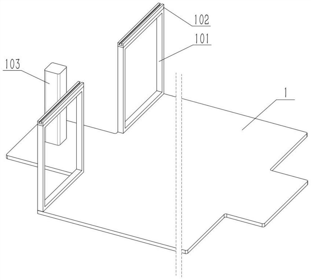
[0048] As shown in the figure, the preparation device of the permanent magnet alloy material also includes a steel frame 101, a grooved guide seat 102, a base 103, a main rod 4, a push rod 401, a shaft II 402, a displacement seat 403, a wedge-shaped guide block 404 and The dial 405 is fixed to the base 1 with two steel frames 101 symmetrically arranged front and back, and a grooved guide seat 102 is fixed to the upper ends of the two steel frames 101, and the base 103 is fixed to the base 1, and the base 103 is located at On the left side of the steel frame 101, the steel frame 101 is located on the left side of the preparation table 2, the lower end of the main rod 4 is driven by the output shaft of the motor II, and the motor II is fixed on the base 103, and the upper end of the main rod 4 is connected to two The upper end of a pull push rod 401, the lower ends of the two pull push rods 401 are rotatably connected to a shaft II 402, a displacement seat 403 is fixed on the two...
PUM
 Abstract
Description
Claims
Application Information
 - R&D
- Intellectual Property
- Life Sciences
- Materials
- Tech Scout
- Unparalleled Data Quality
- Higher Quality Content
- 60% Fewer Hallucinations
Browse by: Latest US Patents, China's latest patents, Technical Efficacy Thesaurus, Application Domain, Technology Topic, Popular Technical Reports.
© 2025 PatSnap. All rights reserved.Legal|Privacy policy|Modern Slavery Act Transparency Statement|Sitemap|About US| Contact US: help@patsnap.com


