

Double-station optical fiber marking device for manufacturing laser devices
A double-station, laser technology, applied in the direction of manufacturing tools, laser welding equipment, metal processing equipment, etc., can solve the problems of temperature rise, no marking device, and only one marking device, so as to prevent the temperature from being too high , Improve production efficiency and prevent ash fall
- Summary
- Abstract
- Description
- Claims
- Application Information
AI Technical Summary
Problems solved by technology
Method used
Image

Examples
Embodiment 1
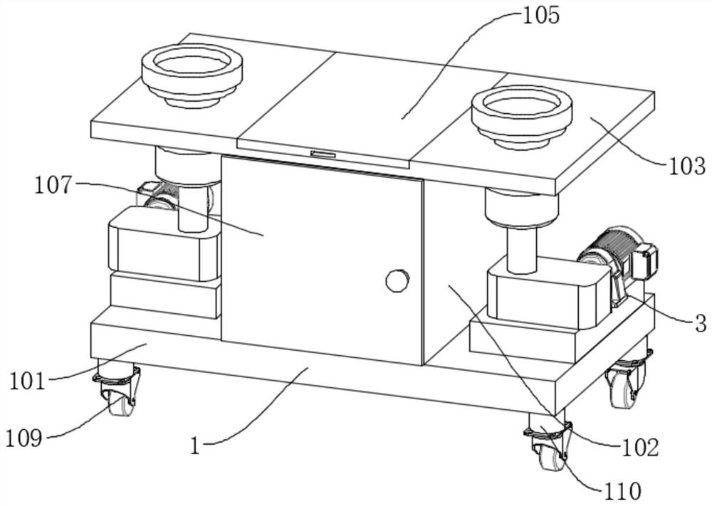
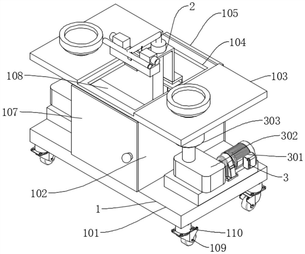
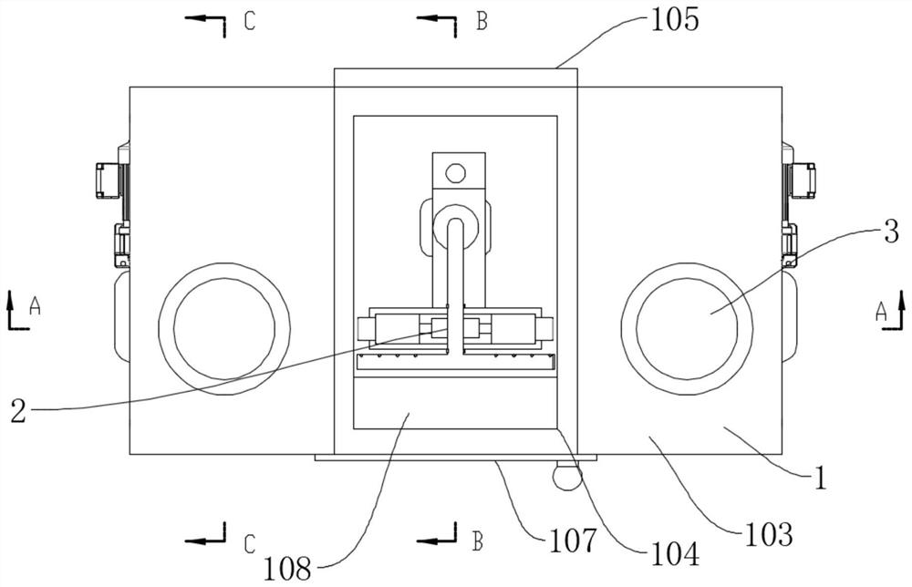
[0036] Such as Figure 1-7 As shown, a dual-station optical fiber marking device for laser manufacturing includes a device body 1, a marking mechanism 2, and a fixture 3. The device body 1 includes a bottom plate 101, a vertical plate 102, a top plate 103, a relief port 104, Top door 105, two opposite vertical plates 102 are welded on the top of the bottom plate 101, a top plate 103 is welded on the top of the vertical plate 102, a groove is opened in the center of the top of the top plate 103, a relief opening 104 is opened in the center of the groove, and the rear end of the groove is A top door 105 is connected through a hinge, and the marking mechanism 2 includes a cylinder 201, a mounting plate 202, a stable structure 203, a driving assembly 204, a marking device body 205, and a cooling assembly 206. The cylinder 201 is connected to the top of the bottom plate 101 by bolts, and is located Between the two vertical plates 102, a mounting plate 202 is connected by bolts abov...
Embodiment 2
[0039] Such as Figure 8 As shown, the difference between Embodiment 2 and Embodiment 1 is that the driving assembly 204 includes a slide rail 2041, a slider 2043, a positive and negative screw 20401, and a rotating disc 20402. The slide rail 2041 is connected to the front end of the top of the mounting plate 202 by bolts. The inside of the slide rail 2041 is connected with positive and negative lead screws 20401 through bearings, and the two ends of the positive and negative lead screws 20401 are threadedly connected with sliders 2043, and a marking device body 205 is installed on the top of each slider 2043, and the positive and negative lead screws 20401 One end stretches out slide rail 2041, and is connected with rotating disk 20402 by bolt, can be arranged like this by rotating rotating disk 20402, and rotating disk 20402 drives positive and negative leading screw 20401 to rotate, and positive and negative leading screw 20401 mobilizes slide block 2043 to move, and slide b...
PUM
 Abstract
Description
Claims
Application Information