
Broken shaft repairing method

A repair method and broken shaft technology, which is applied in the field of equipment repair, can solve problems such as equipment downtime, load-bearing torsional shear force difference, and influence on normal production, and achieve the effects of reducing downtime costs, increasing service life, and reducing repair costs

Inactive Publication Date: 2020-12-15
GUANGDONG GUANGDONG SHAOGANG ENG TECH
View PDF6 Cites 0 Cited by
  • Summary
  • Abstract
  • Description
  • Claims
  • Application Information

AI Technical Summary

Problems solved by technology

However, the conventional repair method has the following disadvantages: 1. The groove is circularly welded in the circumferential direction, the torsion force on the weld seam and the shaft head is consistent, the bearing torsional shear force is poor, and the service life after repair is not long (generally 1 week to 1 month) months), causing equipment downtime and affecting normal production; 2. Frequent repairs, dismantling, transportation, repairing, assembling and other costs of rollers and the cost of downtime and delays are very high, which is not conducive to production cost control

Method used


Image

  • Broken shaft repairing method
  • Broken shaft repairing method
  • Broken shaft repairing method

Examples


Embodiment

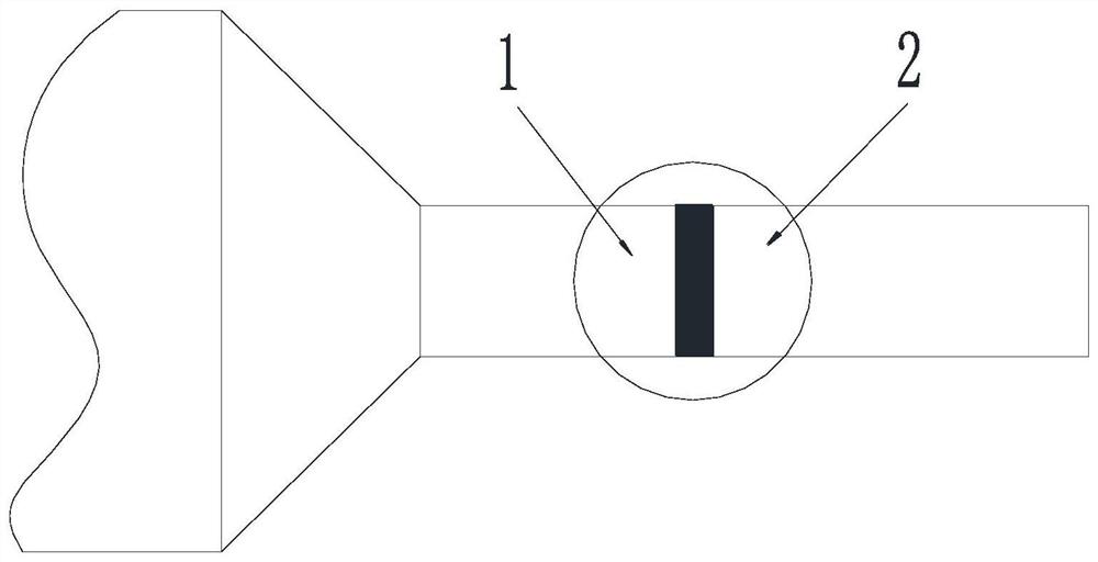
[0043] A broken shaft repair method, comprising:

[0044] Steps for preparing materials: Use the repair section with the same material and heat treatment method as the broken shaft section; the broken shaft section is made of 45# steel, and the quenched and tempered hardness is HB215-240, then the material of the repair section is also 45# steel. The hardness is HB215-240.

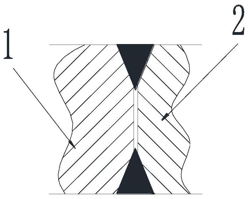
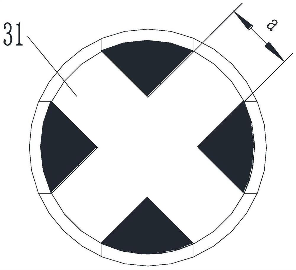
[0045] Milling steps: mill a cross groove on the end face of the broken shaft section, the groove runs through the end face of the broken shaft section, that is, the groove runs through the end face in the length direction, and a convex part is milled on the end face of the repaired section. grooves to match;

[0046] Among them, the diameter of the broken shaft section to be repaired is 100mm, the size of the groove is: the width of the groove is a=23mm, and the bring-in tolerance is The groove depth h = 25mm, and the bring-in tolerance is Then the corresponding convex part size: convex part width a1...


PUM


Abstract

The invention discloses a broken shaft repairing method. The method includes the following steps that a material preparation step is performed, specifically, a repairing section is prepared and is used for repairing a broken shaft section; a milling step is performed, specifically, a groove / convex part is milled in the end surface of the broken shaft section, a convex part / groove is milled in theend surface of the repairing section, and the shape and size of the convex part are matched with those of the groove; a grooving step is performed, specifically, a groove is formed along the outer edge of the end surface of the broken shaft section, and a groove is formed along the outer edge of the end surface of the repairing section; a welding step is performed, specifically, the convex part and the groove are inlaid in a matched manner, are fixed through spot welding and then are welded, and broken shaft repairing is completed. According to the repairing method, the inlaying shape is improved, the welding step is adjusted, the rigidity is good after a shaft or a roller is repaired, and the machining process is simple.

Description

technical field [0001] The invention relates to the field of equipment repair, and more particularly, to a broken shaft repair method. Background technique [0002] In the production system, a large number of shaft and roller parts are used, and the failure due to shaft head breaking takes up a large proportion every year. For example, for the conveying rollers used in the wide plate production line, when the sheet is being rolled, the billet must be continuously rolled back and forth on the rolling rolls, and the back and forth movement of the billet is realized by the frequent forward and reverse rotation of the conveying roller. accomplish. Under the action of its own weight and driving force, the frequent forward and reverse rotation of the roller causes a large torsional shear force between the shaft head and the roller body. When the roller is used for a period of time, when a certain part of the shaft head reaches the fatigue limit, the shaft will appear. The failur...

Claims


Application Information

Patent Timeline
Patent Type & Authority Applications(China)
IPC IPC(8): B23P6/04
CPCB23P6/04
Inventor 谭志尉韩赞文宁华立何龙日刘美剑唐柏杨董涛涛何海波陈锦辉范长江张昊王川袁泉江岳书瓷
Owner GUANGDONG GUANGDONG SHAOGANG ENG TECH
Learn More