Self-supporting optical cable sheath extrusion die

A technology of self-supporting optical cable and extrusion die, which is applied in the direction of optics, light guides, optical components, etc., can solve the problems of accelerated aging, uneven protective cover, long span distance, etc., and achieve the effect of reducing particle backflow

Inactive Publication Date: 2020-12-15
北京鸿运汇商贸有限公司
View PDF5 Cites 3 Cited by
  • Summary
  • Abstract
  • Description
  • Claims
  • Application Information

AI Technical Summary

Problems solved by technology

[0002] In long-distance communication, due to the long distance and the need to bear the load of itself and the outside world, self-supporting optical cables are often used for information transmission. Since the optical cables are installed outdoors for a long time, polyethylene optical cable protective sleeves are used to protect the optical fibers inside the optical cables. The polyethylene is heated and extruded through the sheath extrusion die to make a sheath, and then the cable is passed through the inside of the sheath; in the prior art, when the sheath extrusion die is used to extrude heated polyethylene, since the mold is made of steel Absorb a lot of heat, causing the temperature inside the mold to be higher than the temperature of the injection port and outlet of the mold, and the heat resistance of polyethylene is not high. When the polyethylene passes through the mold, the temperature is too high and the polyethylene is easy to burn , the burnt particles are stuck on the inner wall of the mold, resulting in uneven outer surface of the protective sleeve extruded later, accelerating the reaction with air and aging, and reducing the service life of the protective sleeve

Method used


Image

  • Self-supporting optical cable sheath extrusion die
  • Self-supporting optical cable sheath extrusion die
  • Self-supporting optical cable sheath extrusion die

Examples


Embodiment 1

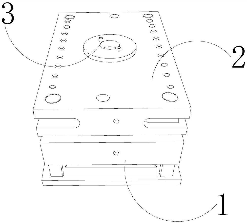
[0025] as attached figure 1 to attach Figure 5 Shown:

[0026] The invention provides a self-supporting optical cable sheath extrusion die, the structure of which includes a support base 1, an upper module 2, and an injection port 3, the upper module 2 is movably matched with the top of the support base 1, and the injection port 3 runs through the upper Module 2 top center position.

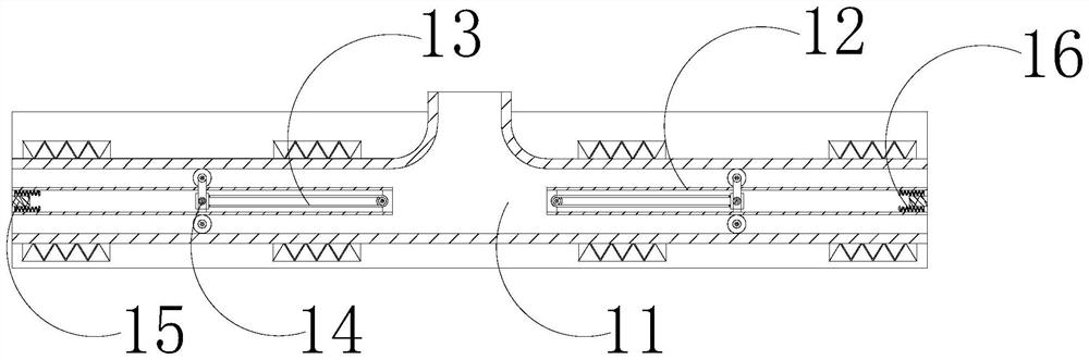
[0027] The support base 1 is provided with a forming cavity 11, a hollow tube 12, a pull rod 13, a removal block 14, a magnetic block 15, and a spring 16. The forming cavity 11 is located inside the support base 1, and the hollow tube 12 is installed on the support base. 1. On both sides of the inner center, the cleaning block 14 is connected to the inner wall of the hollow tube 12 through the pull rod 13, the magnetic block 15 is fixed in the middle of the inner wall on both sides of the hollow tube 12, and the spring 16 is installed on the upper and lower sides of the magnetic block 15.

[...

Embodiment 2

[0034] as attached Image 6 to attach Figure 7 Shown:

[0035]Wherein, the clamping block s6 is provided with a pull rope r1, an elastic block r2, a baffle r3, a chip inlet r4, and a collecting block r5, and the elastic blocks r2 are respectively installed on the left inner wall of the clamping block s6, and the baffle r3 Cooperate with the elastic block r2, the pull rope r1 is installed between the baffle plate r3 and the inner wall on the right side of the clamp block s6, the chip inlet r4 runs through the upper and lower sides of the clamp block s6, and the collection block r5 is fixed on the clamp block In the central position inside s6, the collection block r5 is trapezoidal in shape, which is conducive to increasing the collection volume inside the collection block r5, and the particles roll along the inside of the collection block r5 to reduce the backflow of particles.

[0036] Wherein, the collection block r5 is provided with an opening t1, a collection ring t2, a ...


PUM


Abstract

The invention discloses a self-supporting optical cable sheath extrusion die which structurally comprises a supporting seat, an upper module and an injection molding port. The upper module is movablymatched with the top of the supporting seat. When the die is used for injection molding of a sheath, as a polypropylene solution is easy to be scorched into particles and accumulated on the inner wallof a forming cavity, the polypropylene solution flows to push an eliminating block to move along the inner wall of the forming cavity and a brushing block on the top of a moving block of the eliminating block eliminates the scorched particles on the inner wall of the forming cavity to reduce the probability that the scorched particles are accumulated on the inner wall of the forming cavity, so that injection forming of the sheath is protected favorably. A using time of the protecting sheath is not changed. As the particles brushed by the brushing block fall downward and are easily blended inthe solution, the scorched particles in a clamping block are collected, and the scorched particles blended in the solution are reduced, so that the quality of injection molding of the protecting sheath is protected. A baffle plate changes along with a moving position of an eliminating ring, so that a chip inlet of the clamping block is opened and closed, and therefore, the particles are collectedfavorably and backflow of the particles is reduced.

Description

technical field [0001] The invention belongs to the field of moulds, and more specifically relates to a self-supporting optical cable sheath extrusion die. Background technique [0002] In long-distance communication, due to the long distance and the need to bear the load of itself and the outside world, self-supporting optical cables are often used for information transmission. Since the optical cables are installed outdoors for a long time, polyethylene optical cable protective sleeves are used to protect the optical fibers inside the optical cables. The polyethylene is heated and extruded through the sheath extrusion die to make a sheath, and then the cable is passed through the inside of the sheath; in the prior art, when the sheath extrusion die is used to extrude heated polyethylene, since the mold is made of steel Absorb a lot of heat, causing the temperature inside the mold to be higher than the temperature of the injection port and outlet of the mold, and the heat r...

Claims


Application Information

Patent Timeline
Patent Type & Authority Applications(China)
IPC IPC(8): B29C48/30B29C48/27G02B6/44B29K23/00
CPCB29C48/3001B29C48/272G02B6/4479B29K2023/12
Inventor 黄炳煌
Owner 北京鸿运汇商贸有限公司
Why Eureka
Try Eureka