
Feedback current control device and aerial work vehicle

A current control and current technology, which is applied in the direction of electrical devices, circuit devices, battery circuit devices, etc., can solve problems such as limited effect, long heating time, and low power of heating devices, so as to improve safety and reduce The probability of lithium analysis and the effect of avoiding the risk of lithium analysis

Active Publication Date: 2022-03-29
ZOOMLION INTELLIGENT ACCESS MASCH CO LTD
View PDF6 Cites 0 Cited by
  • Summary
  • Abstract
  • Description
  • Claims
  • Application Information

AI Technical Summary

Problems solved by technology

However, the power of the heating device is limited by various factors, and the temperature rise rate is usually around 10°C / h
When the temperature is low, the time required for heating is longer, which affects the use of equipment by customers
In addition, since aerial work vehicles usually work intermittently, the shutdown interval is long, and the battery temperature is difficult to maintain (the battery temperature cannot be guaranteed to be kept above 0°C during discharge), so this method is not effective and the user experience is poor. Existing technologies have very limited effect on reducing the risks of pulse charging at low temperatures

Method used


Image

  • Feedback current control device and aerial work vehicle
  • Feedback current control device and aerial work vehicle
  • Feedback current control device and aerial work vehicle

Examples


Embodiment Construction

[0037] Specific embodiments of the present invention will be described in detail below in conjunction with the accompanying drawings. It should be understood that the specific embodiments described here are only used to illustrate and explain the present invention, and are not intended to limit the present invention.

[0038] Before introducing specific embodiments of the present invention, two concepts are briefly described.

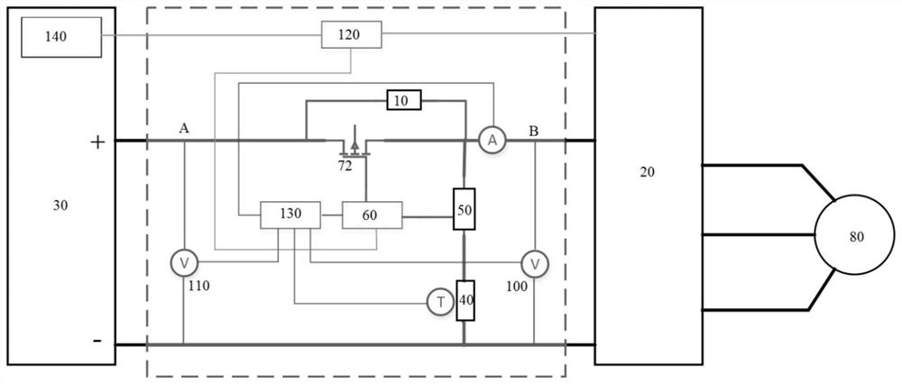
[0039] Regenerative braking: When the electric vehicle brakes, the (walking) electric motor can be controlled to operate as a generator, thereby converting the kinetic energy or potential energy of the vehicle into electrical energy and storing it in the energy storage module.

[0040] Feedback current: During regenerative braking, the driver converts the electric energy generated by the (walking) motor into a current that can be used by the energy storage module or other energy-consuming components. This current is called the feedback current.

[0041...


PUM


Abstract

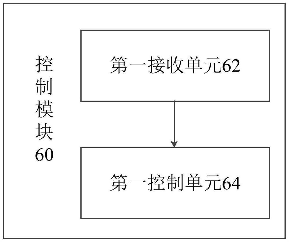
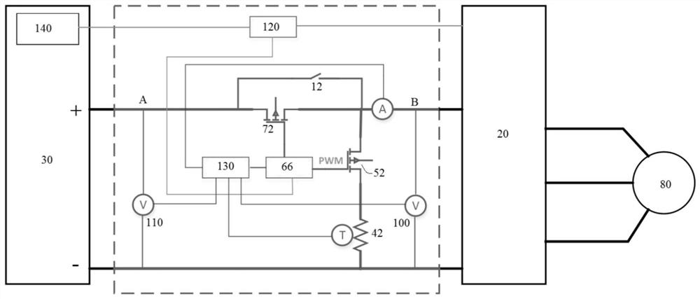
The invention relates to the technical field of engineering machinery, and discloses a feedback current control device and an aerial work vehicle. The feedback current control device includes: a feedback current capture module, which is located on a current capture circuit, and is used to capture the feedback current; a first switch module , used to turn on or off the current capture circuit; and a control module, which includes: a first receiving unit, used to receive the first voltage at one end of the driver on the power supply circuit, the second voltage at one end of the battery and the temperature of the battery; A control unit for performing the following operations according to the difference between the first voltage and the second voltage and the temperature of the battery: when the difference between the first voltage and the second voltage is greater than a preset voltage and the temperature of the battery is less than or equal to a preset When the temperature is set, the current capture circuit is turned on by controlling the first switch module, so that the feedback current capture module captures the feedback current. The invention can greatly reduce the probability of lithium precipitation in the battery and the risk of thermal runaway of the battery.

Description

technical field [0001] The invention relates to the technical field of engineering machinery, in particular to a feedback current control device and an aerial work vehicle. Background technique [0002] Since electric drive aerial work vehicles (self-propelled) usually do not have mechanical friction brakes, the deceleration and parking of the aerial work vehicles rely on energy feedback regenerative braking technology. However, the regenerative braking technology has the following two characteristics: 1. The travel motor driver is both an inverter and a rectifier. When the aerial work vehicle decelerates or goes downhill, it converts kinetic energy into electrical energy, and then feeds the converted electrical energy back to the power Battery; 2. The deceleration and braking time of aerial work vehicles is usually short, and the maximum speed is usually about 6KM / H, and the instantaneous pulse feedback current generated by braking is usually relatively large. Therefore, f...

Claims


Application Information

Patent Timeline
Patent Type & Authority Patents(China)
IPC IPC(8): B60L7/10B60L3/00H02J7/00H02J7/14
CPCB60L7/10B60L3/0046H02J7/1492H02J7/00302H02J7/00309H02J7/007194H02J7/0048Y02T10/92H02J7/1446H02J7/007182H02J2310/48B60L53/22B60L2240/545B60L2240/547B60L2240/549B60L15/2018B60L58/15B60L1/20B60L7/22B60L58/24B60L2200/44B60L2240/429
Inventor 任会礼钟懿朱后熊路孙卫平
Owner ZOOMLION INTELLIGENT ACCESS MASCH CO LTD
Learn More