
Cycloid oscillating tooth speed reducer with mechanical balance combined tooth surface raceway

A technology of movable tooth reducer and mechanical balance, applied in the field of movable tooth transmission, can solve the problems of increasing the difficulty of structural design and manufacturing of parts, and achieve flexible configuration, high torque/volume ratio, and improved rigidity of the whole machine. Effect

Inactive Publication Date: 2020-12-15
HENAN ZHULONG HI TECH CO LTD
View PDF2 Cites 3 Cited by
  • Summary
  • Abstract
  • Description
  • Claims
  • Application Information

AI Technical Summary

Problems solved by technology

Since the driving part of the cycloidal movable tooth transmission mechanism is an eccentric component with a large moment of inertia, the vibration problem of the whole machine has become a thorny problem that needs to be effectively solved under the working conditions of high speed and heavy load. The existing common method is to The mechanism is mechanically balanced and counterweighted, which increases the difficulty of structural design and manufacturing of parts

Method used


Image

  • Cycloid oscillating tooth speed reducer with mechanical balance combined tooth surface raceway
  • Cycloid oscillating tooth speed reducer with mechanical balance combined tooth surface raceway
  • Cycloid oscillating tooth speed reducer with mechanical balance combined tooth surface raceway

Examples


Embodiment Construction

[0031] The technical solutions of the present invention will be further specifically described below through the embodiments and in conjunction with the accompanying drawings.

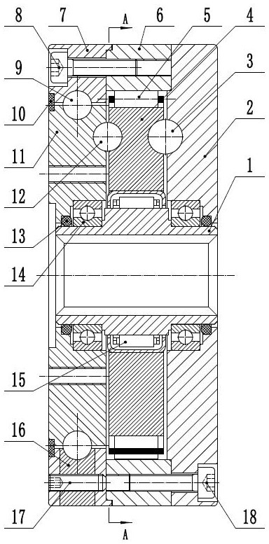
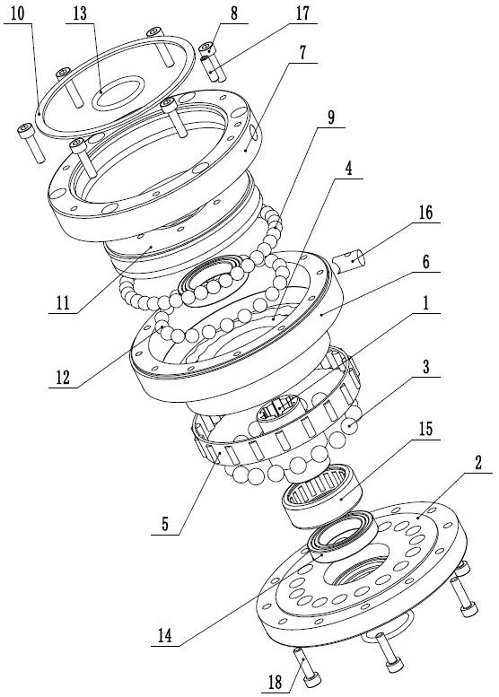
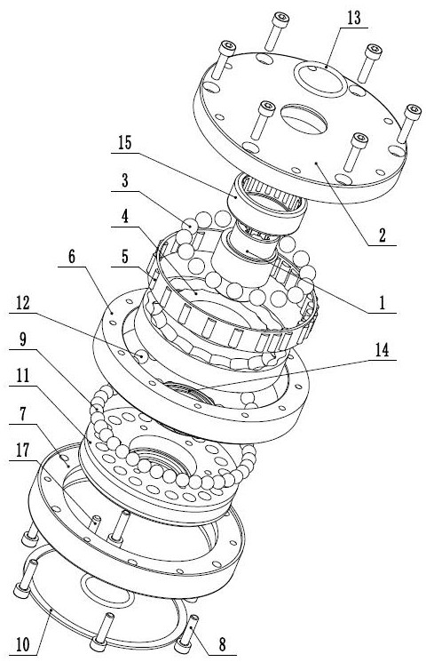
[0032] Figure 1-12 As a preferred embodiment of the present invention, the pictographic method is used to obtain symbolic meanings, the symbol "S" is used to represent the cycloidal raceway of the combined tooth surface, and the symbol "O" is used to represent the movable tooth groove, and S and the corresponding O are connected together to form a The movable tooth meshing pair and the movable tooth constitute a single-stage combined tooth surface raceway cycloid movable tooth transmission unit. As can be seen from the foregoing, the first movable tooth meshing pair, the second movable tooth meshing pair, the third movable tooth meshing pair, and the fourth movable tooth meshing pair, there are four in total, that is, two groups of movable tooth meshing pairs, which are respectively connected with the...


PUM


Abstract

The invention provides a cycloid oscillating tooth speed reducer with a mechanical balance combined tooth surface raceway. The cycloid oscillating tooth speed reducer comprises an input shaft, a fixedoscillating gear, a transition oscillating gear, an output oscillating gear, a first-stage steel ball oscillating tooth, a second-stage steel ball oscillating tooth, a mechanical balance rolling body, densely-arranged steel balls and the like, wherein a transmission mechanism is composed of a two-stage differential cycloid oscillating tooth transmission unit, and movement of the transition oscillating gear serves as input of a two-stage transmission part, the mechanical balance rolling body is mounted on the outer side of the transition oscillating gear and used for reducing the rotational inertia of the whole machine and increasing the rigidity, the output end of the speed reducer adopts a densely-arranged steel ball bearing structure, so that the processing cost is reduced, the cycloidraceway adopts a root cutting tooth surface raceway or a combined tooth surface raceway, and the root cutting tooth surface raceway can be regarded as a special form of the combined tooth surface raceway, so that the cycloid raceway is collectively called as the combined tooth surface raceway, the combined tooth surface raceway is divided into the hypocycloid raceway and the epicycloid raceway, sothat sixteen configurations can be formed through permutation and combination, the configuration modes are flexible and variable, and the transmission ratio range is wide.

Description

technical field [0001] The invention relates to the technical field of movable tooth transmission, in particular to a cycloidal movable tooth reducer with mechanically balanced combined tooth surface raceways. Background technique [0002] Aiming at the shortcomings of the traditional cycloid movable tooth transmission structure design, the present invention creatively proposes the undercut tooth surface raceway movable tooth transmission technology and the combined tooth surface raceway movable tooth transmission technology. Among them, strictly speaking, the undercut tooth surface raceway movable tooth transmission technology can also be classified as a kind of combined tooth surface raceway movable tooth transmission technology. Compared with the traditional cycloid movable tooth transmission, the above-mentioned technology has more movable teeth and a larger transmission ratio under the same size, and basically achieves full-circle meshing force of all teeth, and its com...

Claims


Application Information

Patent Timeline
Patent Type & Authority Applications(China)
IPC IPC(8): F16H1/32F16H49/00F16H57/029F16H57/031F16H57/08F16H55/08F16H55/17F16F15/14
CPCF16F15/1464F16H1/32F16H49/001F16H55/08F16H55/17F16H57/029F16H57/031F16H57/08F16H2001/327F16H2001/328F16H2055/176F16H2057/085
Inventor 闫济东邢鹏达
Owner HENAN ZHULONG HI TECH CO LTD
Learn More