Aluminum material image defect detection method based on self-adaptive anchor frame
A defect detection and self-adaptive technology, applied in the field of computer vision and defect detection, can solve the problems of inflexible detection methods and poor detection methods
- Summary
- Abstract
- Description
- Claims
- Application Information
AI Technical Summary
Problems solved by technology
Method used
Image

Examples
Embodiment Construction
[0082] Below in conjunction with accompanying drawing, the present invention is further described:
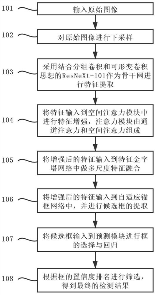
[0083] see figure 1 , the present invention comprises the following steps:
[0084] Step 101, using a camera to acquire image data or directly uploading image data as image input.
[0085] Step 102, perform s times downsampling operation on the original image (W×S) to obtain an image of size (W / s)×(H / s).
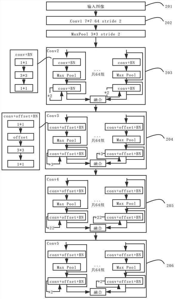
[0086] Step 103, using ResNeXt-101 combined with group convolution and deformable convolution as the backbone network for feature extraction, and processing the original input image through a convolution layer with a convolution kernel of 7×7 and a batch normalization layer Finally, it is divided into 64 groups and entered into Conv2-Conv5. The group convolution can prevent over-fitting of a specific data set without changing the parameter amount, so as to achieve a more accurate effect.
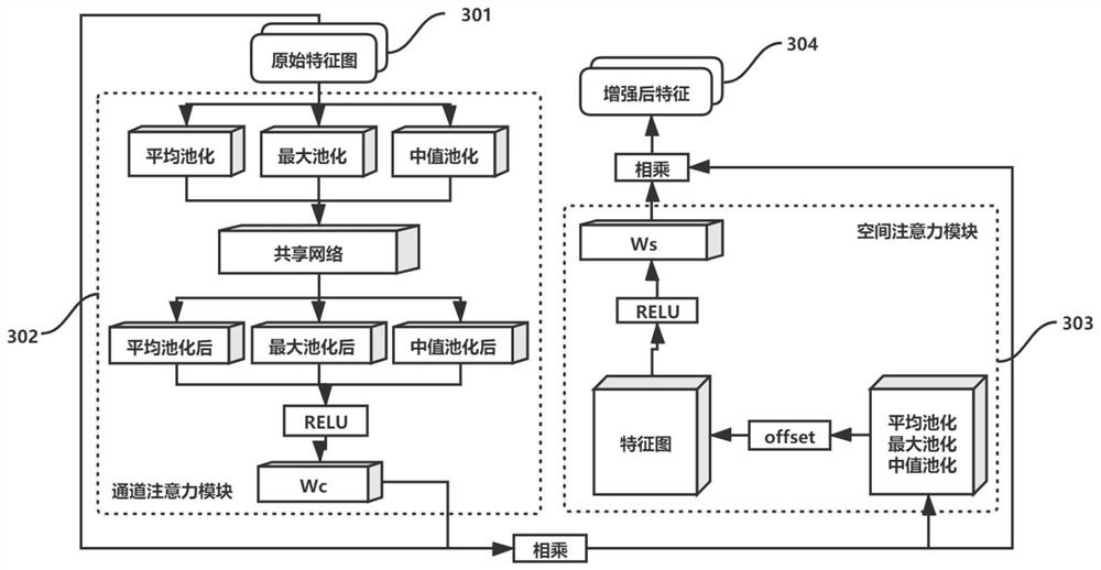
[0087] Step 104, input the features extracted in step 103 into the attention module ...
PUM
 Abstract
Description
Claims
Application Information
 - Generate Ideas
- Intellectual Property
- Life Sciences
- Materials
- Tech Scout
- Unparalleled Data Quality
- Higher Quality Content
- 60% Fewer Hallucinations
Browse by: Latest US Patents, China's latest patents, Technical Efficacy Thesaurus, Application Domain, Technology Topic, Popular Technical Reports.
© 2025 PatSnap. All rights reserved.Legal|Privacy policy|Modern Slavery Act Transparency Statement|Sitemap|About US| Contact US: help@patsnap.com