
A power factor correction circuit and its correction method

A power factor correction and circuit correction technology, which is applied in the direction of output power conversion device, AC power input conversion to DC power output, electrical components, etc., can solve low THD value, input current distortion, total harmonic distortion affecting the circuit, etc. problem, achieve the effect of reducing THD value and reducing impact

Active Publication Date: 2022-03-18
MORNSUN GUANGZHOU SCI & TECH
View PDF0 Cites 0 Cited by
  • Summary
  • Abstract
  • Description
  • Claims
  • Application Information

AI Technical Summary

Problems solved by technology

The input current distortion is serious, which affects the total harmonic distortion (Total Harmonic Distortion, THD) of the circuit, which is not conducive to obtaining a lower THD value

Method used


Image

  • A power factor correction circuit and its correction method
  • A power factor correction circuit and its correction method
  • A power factor correction circuit and its correction method

Examples


Embodiment 1

[0033] Such as Figure 7 As shown, it is a partial circuit schematic diagram of a power factor correction circuit according to an embodiment of the present invention.

[0034] A power factor correction circuit includes a THD correction circuit, and the THD correction circuit includes a compensation voltage source generating circuit 201 and a compensation current limiting circuit 202 .

[0035]The compensation voltage source generation circuit 201 is used to generate a negative compensation voltage source, which includes a first capacitor C1, a third diode D3, a fourth diode D4, and a second capacitor C2. One end of the first capacitor C1 is used as the first input end of the THD correction circuit, the other end of the first capacitor C1 is connected to the anode of the third diode D3 and the cathode of the fourth diode D4, and the end of the fourth diode D4 The anode serves as a port connected to the compensation current limiting circuit 202 and is connected to one end of th...

Embodiment 2

[0055] Figure 9 It is the second embodiment of the present invention.

[0056] The main difference from Embodiment 1 is that a compensation voltage adjustment circuit 204 is added, which is connected in series between the first input signal and the compensation voltage source generation circuit 201, and is used to adjust the output voltage amplitude of the compensation voltage source generation circuit 201 . The compensation voltage adjustment circuit 204 includes a fifth diode D5, a sixth diode D6, a third resistor R3 and a fourth resistor R4.

[0057] Wherein the anode of the fifth diode D5 is connected to the cathode of the sixth diode D6 as the new first input terminal of the THD correction circuit, and is connected to the pulse width signal with high and low level signals, and its input signal is Vpwm , usually the first input end can be connected to the drive signal end or one end of the auxiliary winding of the inductor; the cathode of the fifth diode D5 is connected...


PUM


Abstract

The present invention provides a power factor correction circuit, including a THD correction circuit, the THD correction circuit includes a compensation voltage source generating circuit and a compensation current limiting circuit, the first input terminal of the THD correction circuit is used to access the first input signal, and the THD correction circuit The second input end of the THD correction circuit is used to connect to the output end of the peak current detection unit of the power factor correction circuit, and the output end of the THD correction circuit is used to connect to the logic circuit of the power factor correction circuit. The compensation voltage source generating circuit is used to generate a negative compensation voltage source to provide to the compensation current limiting circuit, and the compensation current limiting circuit is used to limit the magnitude of the compensation current. The invention increases the minimum value of the inductance current of the power factor correction circuit by compensating the current, reduces the distortion effect of the negative current on the input current in the power factor correction circuit, and can obviously reduce the THD value of the power factor correction circuit.

Description

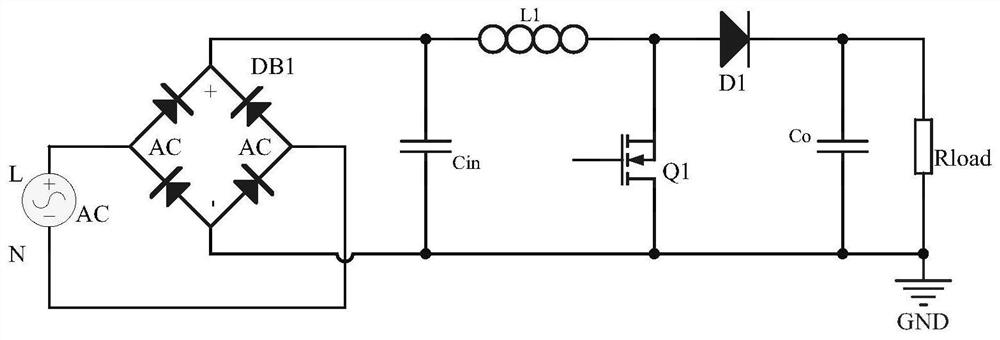
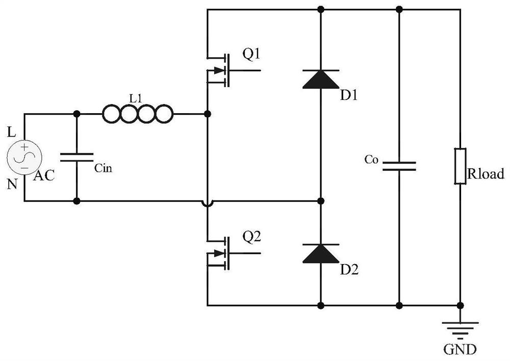
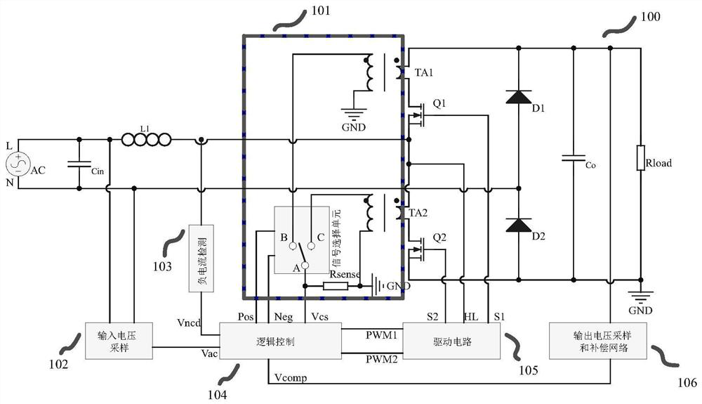
technical field [0001] The invention relates to the field of power factor correction circuits, in particular to a THD correction circuit and a correction method thereof. Background technique [0002] With the rapid development of modern industry, the nonlinear load of power system is increasing day by day. The harmonic current generated by these nonlinear loads is injected into the power grid, which distorts the voltage waveform of the public power grid and seriously pollutes the environment of the power grid. In order to reduce and eliminate harmonics, power factor correction (PowerFactor Correct, PFC) should be performed. Thus, an input current close to a sine wave and a power factor close to 1 are obtained. [0003] figure 1 Shown is a traditional bridged PFC circuit, figure 2 Shown is a totem pole bridgeless PFC circuit. Compared with the traditional bridged PFC circuit, the totem pole bridgeless PFC circuit reduces the loss of the rectifier bridge pile at the input...

Claims


Application Information

Patent Timeline
Patent Type & Authority Patents(China)
IPC IPC(8): H02M1/42H02M7/217
CPCH02M1/4208H02M7/217Y02B70/10
Inventor 何垒宁思捷
Owner MORNSUN GUANGZHOU SCI & TECH
Learn More