Refiner with spiral inlet and dual tangential discharge outlet

a technology of spiral inlet and outlet, which is applied in the field of refiners, can solve the problems of uneven refining, increased wear of the refining plate surface, and increased contact with the plate surface, and achieves the effect of minimal acceleration

Inactive Publication Date: 2010-06-01
ANDRITZ INC
View PDF8 Cites 0 Cited by
  • Summary
  • Abstract
  • Description
  • Claims
  • Application Information

AI Technical Summary

Benefits of technology

[0007]It would be desirable to accelerate the incoming flow more closely to the geometry of the rotating plates of the refiner. It would also be desirable to distribute the incoming flow such that it is more uniformly distributed annularly around the inner periphery of the refining zone. It would also be desirable to configure the refiner discharge such that there would be minimal acceleration required to discharge the slurry flow.
[0011]In yet another exemplary embodiment, a casing for a fibrous slurry refiner includes a pair of outlet channels, one on each side of the casing, wherein the outlet channels are configured to minimize a disturbance on the casing caused by discharge of a refined slurry.

Problems solved by technology

This can result in one zone pulling more than one-half of the total flow being supplied to the refiner, which then provides uneven refining in the two zones since the thrust in the zones and the power applied is equal.
Another deficiency is that the zone with the lower flow will have a smaller operating gap and therefore have a greater tendency for plate contact and increased wearing of the refining plate surfaces.
This problem of uneven flow is particularly noticeable at material flows that are at the minimum volumetric capacity of the machine where operation may be desirable due to the lower refining intensities available at the lower flows.
The required space reduces the effective work area of the machine.

Method used


Image

  • Refiner with spiral inlet and dual tangential discharge outlet
  • Refiner with spiral inlet and dual tangential discharge outlet
  • Refiner with spiral inlet and dual tangential discharge outlet

Examples


Embodiment Construction

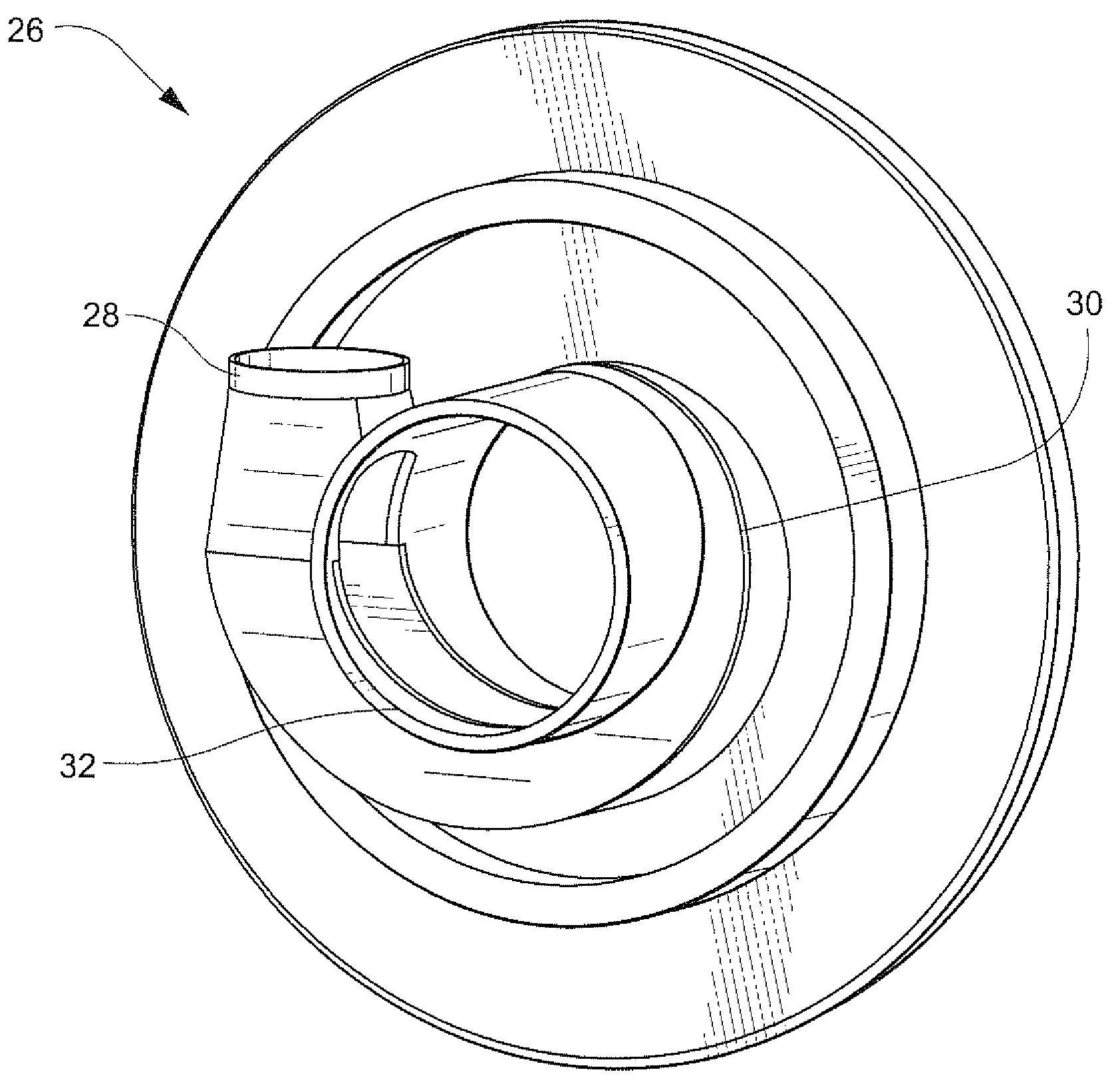
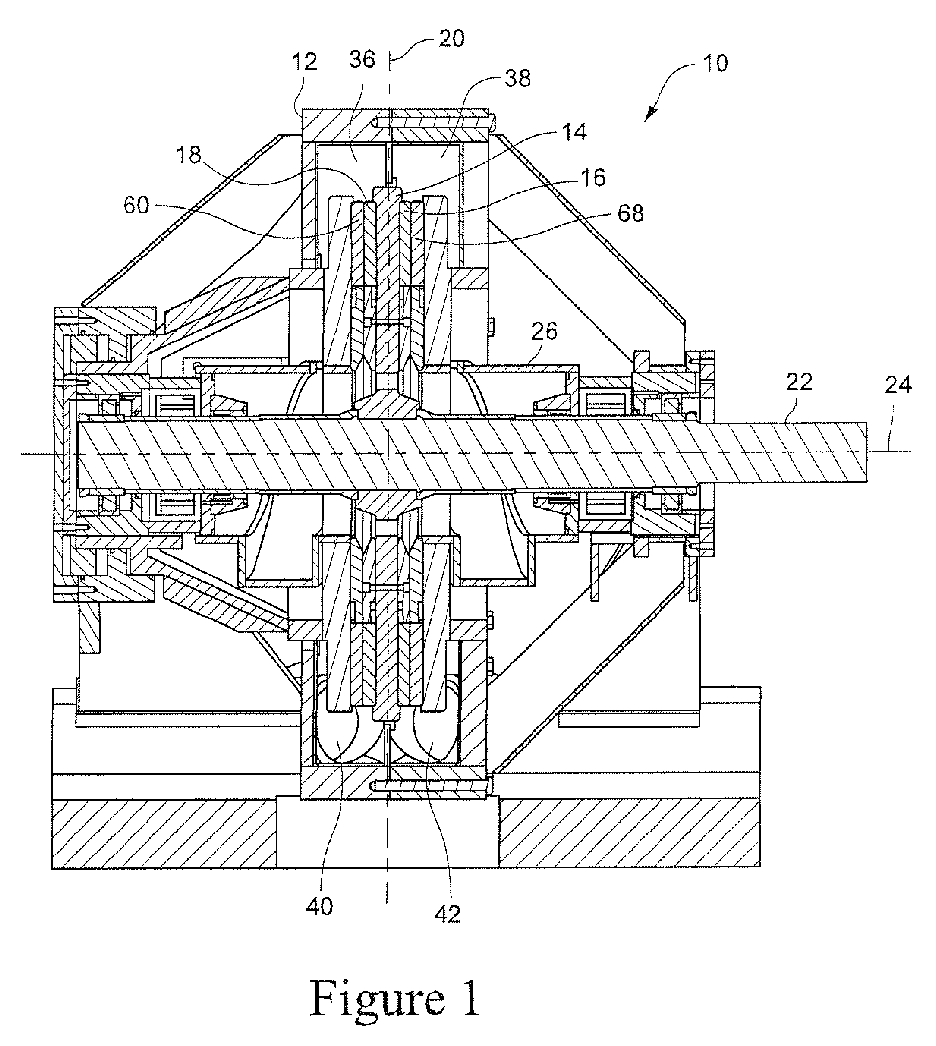
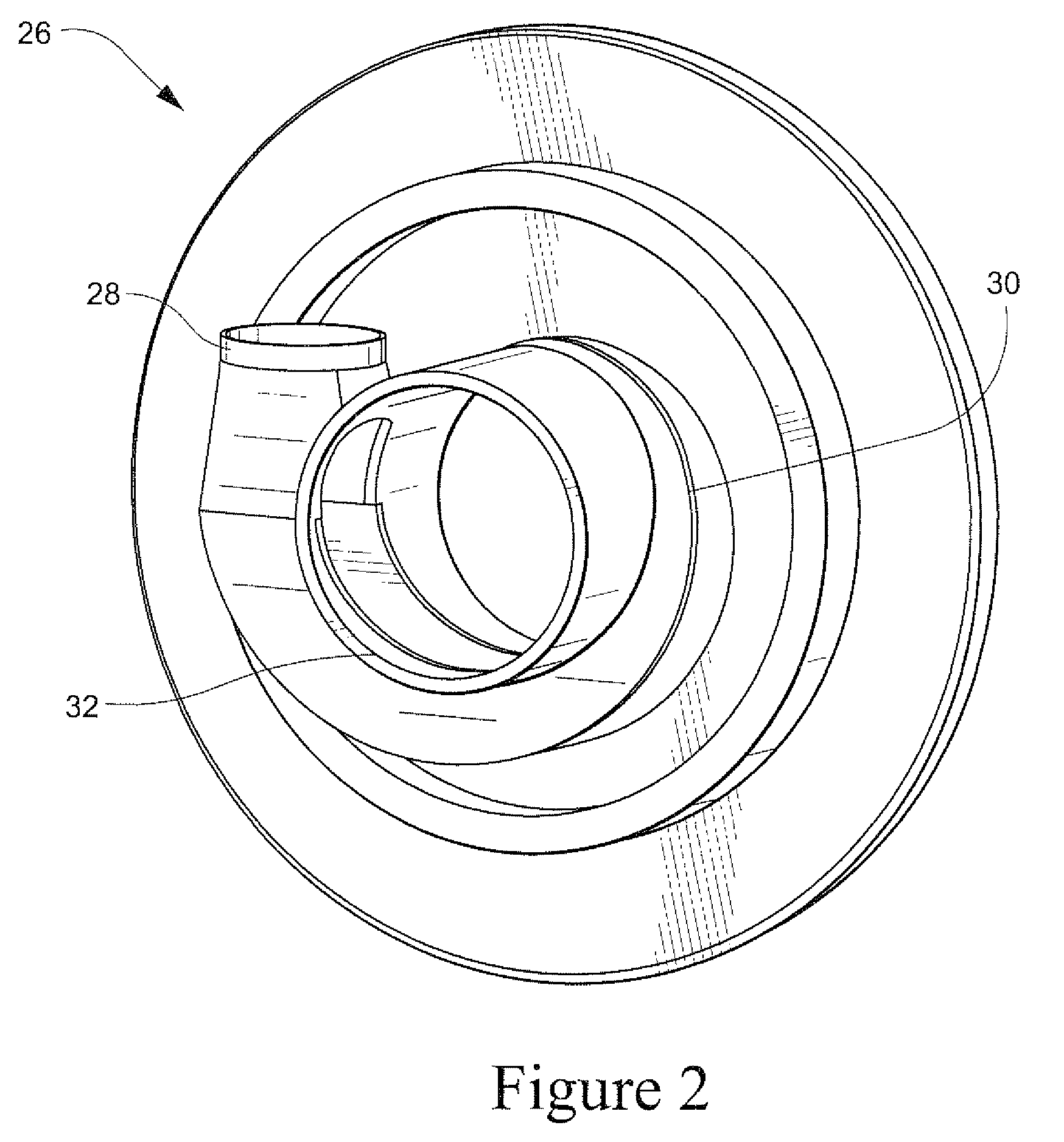
[0018]It should be understood that the present invention is applicable to a variety of refiners for mechanically treating a slurry of fibrous material, wherein the machine has at least two refining zones located substantially symmetrically on either side of a vertical plane perpendicular to the refiner shaft. A refiner 10 of this type is shown in FIG. 1. A casing 12 has a substantially flat rotor 14 situated therein, the rotor carrying a first annular plate defining a first grinding surface 16 and a second annular plate defining a second grinding surface 18, each disposed in facing relation with third and fourth grinding surfaces 68, 60 respectively. A shaft 22 extends horizontally about a rotation axis 24 and is driven at one or both ends (not shown) in a conventional manner. The refiner in FIG. 1 is in all respects pertinent to this disclosure symmetric about plane 20, and therefore any structure described herein on one side of the plane has counterpart structure on the other side...


PUM

PropertyMeasurementUnit
circumferenceaaaaaaaaaa
surface areaaaaaaaaaaa
lengthaaaaaaaaaa

Abstract

A fibrous slurry refiner includes a casing, a rotor secured to a rotor shaft, and first and second pluralities of grinding surfaces. The rotor is disposed within the casing and is rotatable via the rotor shaft. The first plurality of grinding surfaces is secured to the rotor, and the second plurality of grinding surfaces is disposed facing the first plurality of grinding surfaces and fixed in the casing. An inlet plate for each of the plurality of grinding surfaces directs the fibrous slurry toward a set of facing first and second grinding surfaces and imparts a rotary flow to the fibrous slurry.

Description

CROSS-REFERENCES TO RELATED APPLICATIONS[0001]This application claims the benefit of U.S. Provisional Patent Application Ser. No. 60 / 915,802, filed May 3, 2007, the entire content of which is herein incorporated by reference.STATEMENT REGARDING FEDERALLY SPONSORED RESEARCH OR DEVELOPMENT[0002](Not Applicable)BACKGROUND OF THE INVENTION[0003]The present invention relates to a refiner for refining a fibrous slurry and, more particularly, to a refiner including inlet and outlet structure that effects better performance.[0004]Refiners for a fibrous slurry are used for developing fiber to increase surface area and fibrils and for cutting fibers to reduce their length. Low consistency refining was generally understood with respect to lignocellulosic material, as referring to a refiner fed by pumped slurry having a consistency of about 2-5% fiber. Modern pumping techniques accommodate consistency up to about 16% fiber (sometimes referred to as “medium consistency”). In these types of refin...

Claims


Application Information

Patent Timeline
Patent Type & Authority Patents(United States)
IPC IPC(8): B02C7/11
CPCD21D1/303B02C7/02D21D1/30
Inventor KRAFT, MICHAELRUCH, JULIE
Owner ANDRITZ INC
Why Eureka
Try Eureka