Multifunctional workbench for mold design

A mold design and workbench technology, which is applied to the legs of general furniture, the combination and application of two or more different types of furniture, etc., can solve the problems of inconvenient transfer and confusion of tools, and achieve easy rotation and later use. , the effect of rapid heat dissipation

Inactive Publication Date: 2020-12-18
肖常菊
View PDF0 Cites 2 Cited by
  • Summary
  • Abstract
  • Description
  • Claims
  • Application Information

AI Technical Summary

Problems solved by technology

[0003] When the workbench is used for mold design, the drawings are usually placed in a stacked manner, which is easy to cause confusion in the later process. At the same time, th

Method used


Image

  • Multifunctional workbench for mold design
  • Multifunctional workbench for mold design
  • Multifunctional workbench for mold design

Examples


Embodiment 1

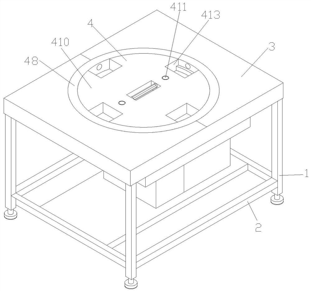
[0026] see Figure 1 to Figure 5 , the present invention provides a multifunctional workbench for mold design through improvement, including a bracket 1 and a reinforcing rod 2, the bracket 1 is installed on the bottom end surface of the workbench 3, and the bottom of the side surface of the bracket 1 is locked with the reinforcing rod 2, which improves the Stability of support 1.

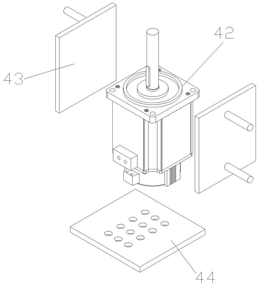
[0027] see figure 2 and image 3 , the present invention provides a multifunctional workbench for mold design through improvement. The rotating mechanism 4 is arranged on the outside of the workbench 3. The rotating mechanism 4 includes a housing 41, a motor 42, a reinforcement frame 43, a bottom plate 44, a partition 45, Label 46, pressing mechanism 47, outer frame 48, fixing mechanism 49, slider 410, guide rod 411, handle 412 and placement groove 413, housing 41 is arranged on the inner bottom end of support 1, the inner left end and right end surface of housing 41 The middle part is hollowed...

Embodiment 2

[0031] The present invention provides a multi-functional workbench for mold design through improvement, four supports 1 are arranged on the bottom end surface of the workbench 3 and four ends, and no two adjacent supports 1 are connected by reinforcing rods 2, so that The workbench 3 is more stable during the placement process. Four reinforcement rods 2 are arranged in a ring shape at the bottom of the workbench 3, and the reinforcement rods 2 at the left and right ends are connected by a square plate, which facilitates the installation of the shell 41 on the top of the square plate .

[0032] The present invention provides a multifunctional workbench for mold design through improvement, and its working principle is as follows;

[0033] First, first place the device as a whole in an appropriate position stably, and connect the motor 42 to an external controller, and then directly carry out corresponding mold design on the top surface of the workbench 3;

[0034] Second, when ...


PUM


Abstract

The invention discloses a multifunctional workbench for mold design. The multifunctional workbench comprises a support and a reinforcing rod. A rotating mechanism is arranged on the outer side of theworkbench, a motor is powered on, an output shaft drives an outer frame and a sliding block to rotate, the sliding block drives a containing groove to rotate, and therefore the containing groove drives a built-in tool to rotate, and use is convenient; and meanwhile, a drawing can be placed on the top end face of a partition plate, the placed drawing is marked and explained through a label, then ahand wheel is rotated to drive a screw to rotate, and therefore a U-shaped frame moves vertically downwards under the action of the screw to clamp and fix the drawing to the top end face of the partition plate, and the beneficial effects that the drawing is rapidly and stably stored, later use is convenient, meanwhile, the tool can be conveniently rotated and used, and convenience is brought to work are achieved.

Description

technical field [0001] The invention relates to the related field of workbenches, in particular to a multifunctional workbench for mold design. Background technique [0002] Mold, various molds and tools used in industrial production for injection molding, blow molding, extrusion, die-casting or forging forming, smelting, stamping and other methods to obtain the required products, and the mold needs to be designed before production, and the mold is designed It is generally completed by a design team. During the design process, team members will work on a desktop to facilitate communication during the work process. The use of corresponding workbenches makes the mold design process more efficient. [0003] When the workbench is used for mold design, the drawings are usually placed in a stacked manner, which is easy to cause confusion in the later process. At the same time, the mold design process sometimes requires the use of special tools. When the workbench is large, the des...

Claims


Application Information

Patent Timeline
IPC IPC(8): A47B27/02A47B13/08A47B11/00A47B83/04A47B63/02A47B97/00H02K5/20
CPCA47B11/00A47B13/08A47B27/02A47B63/02A47B83/045A47B97/00H02K5/20
Inventor 肖常菊
Owner 肖常菊
Why Eureka
Try Eureka