
Machining method for grooving of shaft workpiece

A technology for shaft workpieces and processing methods, which is applied in the field of grooving processing of shaft workpieces, can solve problems such as low processing efficiency, poor consistency, and difficult control of processing accuracy, and achieve improved processing efficiency, simple and convenient operation, and mobile feed high precision effect

Active Publication Date: 2020-12-18
QIJING MACHINERY
View PDF9 Cites 0 Cited by
  • Summary
  • Abstract
  • Description
  • Claims
  • Application Information

AI Technical Summary

Problems solved by technology

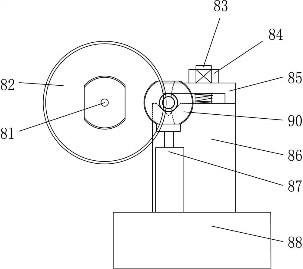
This processing method can only process one slot 92 per clamping, and the processing efficiency is low, and the machining accuracy of the slot 92 of the shaft workpiece 90 is related to the feed movement accuracy driven by the carriage 88, so the machining accuracy is difficult to control , leading to poor consistency in product processing

Method used


Image

  • Machining method for grooving of shaft workpiece
  • Machining method for grooving of shaft workpiece
  • Machining method for grooving of shaft workpiece

Examples


Embodiment Construction

[0023]The present invention will be further described below in conjunction with the drawings and embodiments.

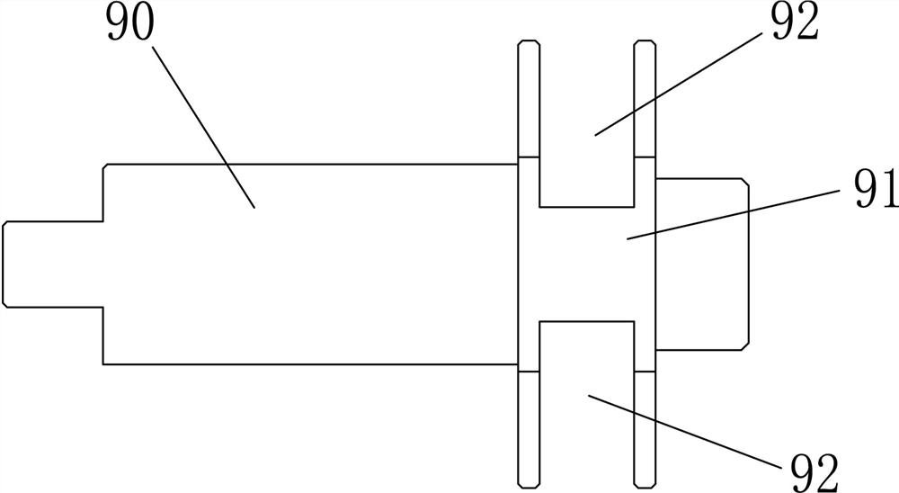
[0024]Such asfigure 1 The shown metal shaft workpiece 90 has a boss portion provided on its peripheral surface. The boss portion has symmetrical cutting planes 91 on its front and back sides, and the boss portion has symmetrical cutting grooves 92 on its upper and lower sides. The processing method of this embodiment is to process the groove 92 of the shaft workpiece 90.

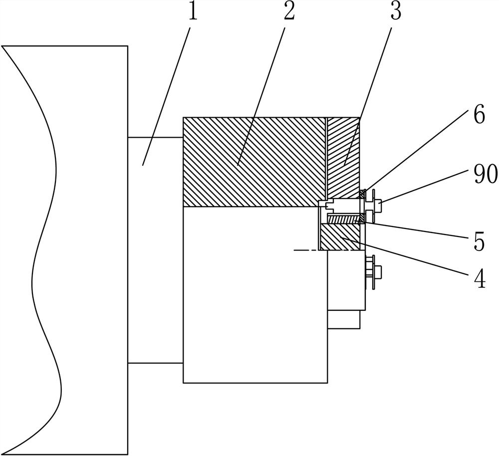
[0025]Seeimage 3 ,Figure 4 withFigure 5 , The processing device of this example includes a main shaft 1, the main shaft 1 is provided with a hydraulic three-jaw chuck 2, the hydraulic three-jaw chuck 2 is connected with three coaxially adjustable clamping claws 3, the clamping claws 3 through the first hexagon socket screw 11 is fixedly connected with the hydraulic three-jaw chuck 2. The hydraulic three-jaw chuck 2 is provided with a screw hole for screwing with the first hexagon socket screw 11, and the hydra...


PUM


Abstract

The invention discloses a machining method for the grooving of a shaft workpiece. A machining device comprises a main shaft; the main shaft is provided with a hydraulic three-jaw clamping disc; the hydraulic three-jaw clamping disc is connected with three clamping jaws; the hydraulic three-jaw clamping disc is coaxially and fixedly connected with a fixing base; the fixing base is provided with mounting grooves corresponding to the three clamping jaws in a one-to-one mode; a pressing cushion block is arranged in each of the mounting grooves; and the fixing base is further fixedly connected witha directional limiting block. According to the machining method for the grooving of the shaft workpiece, the hydraulic three-jaw clamping disc and as corresponding tool clamp are used for clamping shaft workpieces to be machined, and the grooving of the three shaft workpieces can be machined every time clamping is conducted, so that the machining efficiency is greatly improved; and during machining, the hydraulic three-jaw clamping disc is driven by the main shaft to rotate, and cutters only need to conduct corresponding feeding movement, so that the machining precision is high, the machiningefficiency is greatly improved, and the consistency of product processing is good.

Description

Technical field[0001]The invention belongs to the technical field of turning processing of metal material workpieces, and in particular relates to a processing method for grooving shaft workpieces.Background technique[0002]Shaft workpieces are usually cylindrical metal rods, such asfigure 1 The shown metal shaft workpiece 90 has a boss portion provided on its peripheral surface. The boss portion has symmetrical cutting planes 91 on its front and back sides, and the boss portion has symmetrical cutting grooves 92 on its upper and lower sides. When processing the groove 92, the existing processing method is to use a notch milling cutter and a bedroom milling machine for processing, such asfigure 2 As shown, it includes a rotating shaft 81 on which a notch milling cutter disk 82 is provided. A carriage 88 is provided beside the notch milling cutter 82, and a V-shaped fixing seat 86 and a directional tightening mechanism 87 are provided on the carriage 88. , The V-shaped fixing seat 86 ...

Claims


Application Information

Patent Timeline
IPC IPC(8): B23C3/28B23B31/10
CPCB23B31/102B23C3/28B23C2220/36
Inventor 冯海明汪守丰汪东敏
Owner QIJING MACHINERY
Learn More