Centrifugal machine for sewage treatment

A sewage treatment and centrifuge technology, applied in the field of centrifuges, can solve the problems of complicated sewage treatment procedures, time-consuming and laborious, and inconvenient for experimenters to use

Active Publication Date: 2020-12-18
QINGHAI UNIV FOR NATITIES
View PDF6 Cites 0 Cited by
  • Summary
  • Abstract
  • Description
  • Claims
  • Application Information

AI Technical Summary

Problems solved by technology

[0004] The purpose of the present invention is to solve the problem that the sewage treatment procedures in the prior art are co

Method used


Image

  • Centrifugal machine for sewage treatment
  • Centrifugal machine for sewage treatment
  • Centrifugal machine for sewage treatment

Examples


Embodiment 1

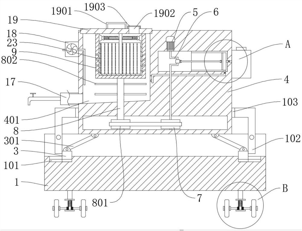
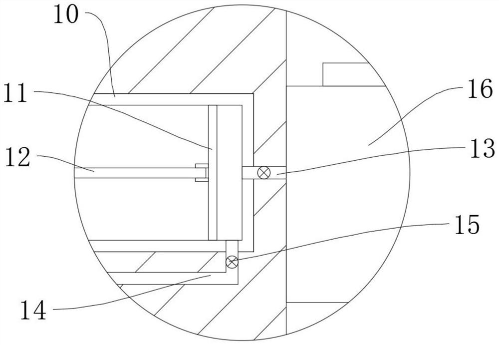
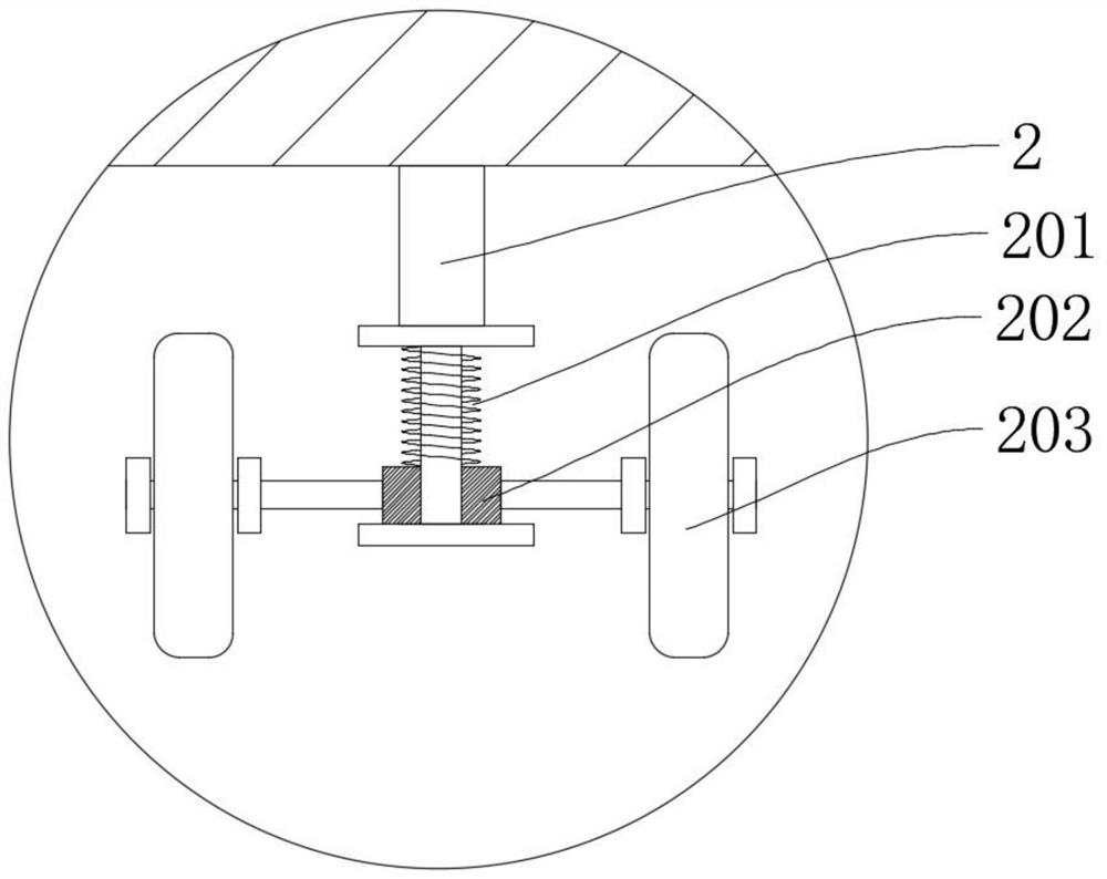
[0033] refer to Figure 1-8 , a centrifuge for sewage treatment, comprising a base 1 and a box body 4, the box body 4 is provided with a water collection cavity 401, a motor 5 is fixedly connected to the box body 4, and a crankshaft 6 and a first crankshaft 6 are fixedly connected to the output end of the motor 5 The pulley 7, the inner wall of the box body 4 is rotatably connected with a rotating shaft 8, the rotating shaft 8 is fixedly connected with a stirring tooth 802 and the drum 9, the inner wall of the box body 4 is fixedly connected with a piston cylinder 10, and the inner wall of the piston cylinder 10 is slidingly connected with a push plate 11, The outer wall of the push plate 11 is rotatably connected with a push rod 12, and the end of the push rod 12 away from the push plate 11 is rotatably connected to the crankshaft 6. The piston cylinder 10 is provided with a feed pipe 13 and a discharge pipe 14. The pipes 14 are provided with one-way valves 15, the box body 4...

Embodiment 2

[0047] refer to Figure 1-8 , a centrifuge for sewage treatment, comprising a base 1 and a box body 4, the box body 4 is provided with a water collection cavity 401, a motor 5 is fixedly connected to the box body 4, and a crankshaft 6 and a first crankshaft 6 are fixedly connected to the output end of the motor 5 The pulley 7, the inner wall of the box body 4 is rotatably connected with a rotating shaft 8, the rotating shaft 8 is fixedly connected with a stirring tooth 802 and the drum 9, the inner wall of the box body 4 is fixedly connected with a piston cylinder 10, and the inner wall of the piston cylinder 10 is slidingly connected with a push plate 11, The outer wall of the push plate 11 is rotatably connected with a push rod 12, and the end of the push rod 12 away from the push plate 11 is rotatably connected to the crankshaft 6. The piston cylinder 10 is provided with a feed pipe 13 and a discharge pipe 14. The pipes 14 are provided with one-way valves 15, the box body 4...


PUM


Abstract

The invention discloses a centrifugal machine for sewage treatment, and belongs to the technical field of centrifugal machines. The centrifugal machine for sewage treatment comprises a base and a boxbody, a water collecting cavity is formed in the box body, a motor is fixedly connected into the box body, a crankshaft and a first belt wheel are fixedly connected to the output end of the motor, a rotating shaft is rotatably connected to the inner wall of the box body, stirring teeth and a rolling barrel are fixedly connected to the rotating shaft, a piston cylinder is fixedly connected to the inner wall of the box body, the inner wall of the piston cylinder is slidably connected with a push plate, the outer wall of the push plate is rotatably connected with a push rod, the end, away from the push plate, of the push rod is rotatably connected to the crankshaft, the piston cylinder is provided with a feeding pipe and a discharging pipe, the feeding pipe and the discharging pipe are each provided with a one-way valve, the box body is provided with a protection cover, the protection cover is placed above the rolling barrel, and a fixing rod is fixedly connected to the bottom outer wallof the protective cover. A sewage sample can be rapidly purified and separated, convenience is provided for experimenters to sample separated solid and liquid, and the experiment efficiency is improved.

Description

technical field [0001] The invention relates to the technical field of centrifuges, in particular to a centrifuge for sewage treatment. Background technique [0002] A centrifuge is a machine that uses centrifugal force to separate components in a mixture of liquid and solid particles or liquid and liquid. The centrifuge is mainly used to separate the solid particles in the suspension from the liquid, or to separate the two densities in the emulsion. , and separate immiscible liquids; it can also be used to remove liquid from wet solids, such as drying wet clothes with a washing machine; special ultra-speed tube separators can also separate gas mixtures of different densities; using different densities or particle sizes Due to the different settling speeds of solid particles in liquids, some decanter centrifuges can also classify solid particles according to density or particle size. [0003] At present, sewage treatment needs to undergo solid-liquid separation through mult...

Claims


Application Information

Patent Timeline
IPC IPC(8): C02F9/04
CPCC02F9/00C02F1/5281C02F1/38C02F1/001C02F2001/007C02F2303/16C02F2303/14
Inventor 安凌云孟雷超
Owner QINGHAI UNIV FOR NATITIES
Why Eureka
Try Eureka