Sponge city road drainage system

A technology of drainage system and sponge city, applied in the field of municipal construction of sponge city, can solve the problems of affecting traffic, increasing the pressure of urban sewage treatment system, reducing the efficiency of rainwater absorption by sponge city, and achieving the effect of ensuring absorption efficiency.

Inactive Publication Date: 2020-12-18
临沂人民公园
View PDF4 Cites 4 Cited by
  • Summary
  • Abstract
  • Description
  • Claims
  • Application Information

AI Technical Summary

Problems solved by technology

[0003] When building a sponge city, it is often necessary to collect rainwater and discharge it to a designated location when it is used. Since the rainwater on the road flows, it often carries a large amount of road pollutants, and the rainwater needs to be treated by the sewage treatment system first. However, if all the rainwater on the road surface is directly discharged into the sewage treatment system, the pressure on the urban sewage treatment system will be sharply increased, resulting in low efficiency of rainwater drainage on the road surface and causing water accumulation on the road, which will not only affect traffic, but also reduce the cost of sponge cities. The absorption efficiency of rainwater

Method used


Image

  • Sponge city road drainage system
  • Sponge city road drainage system
  • Sponge city road drainage system

Examples


Embodiment 1

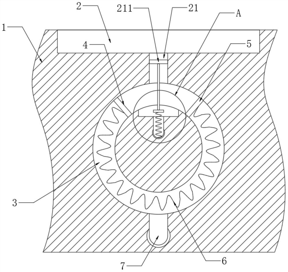
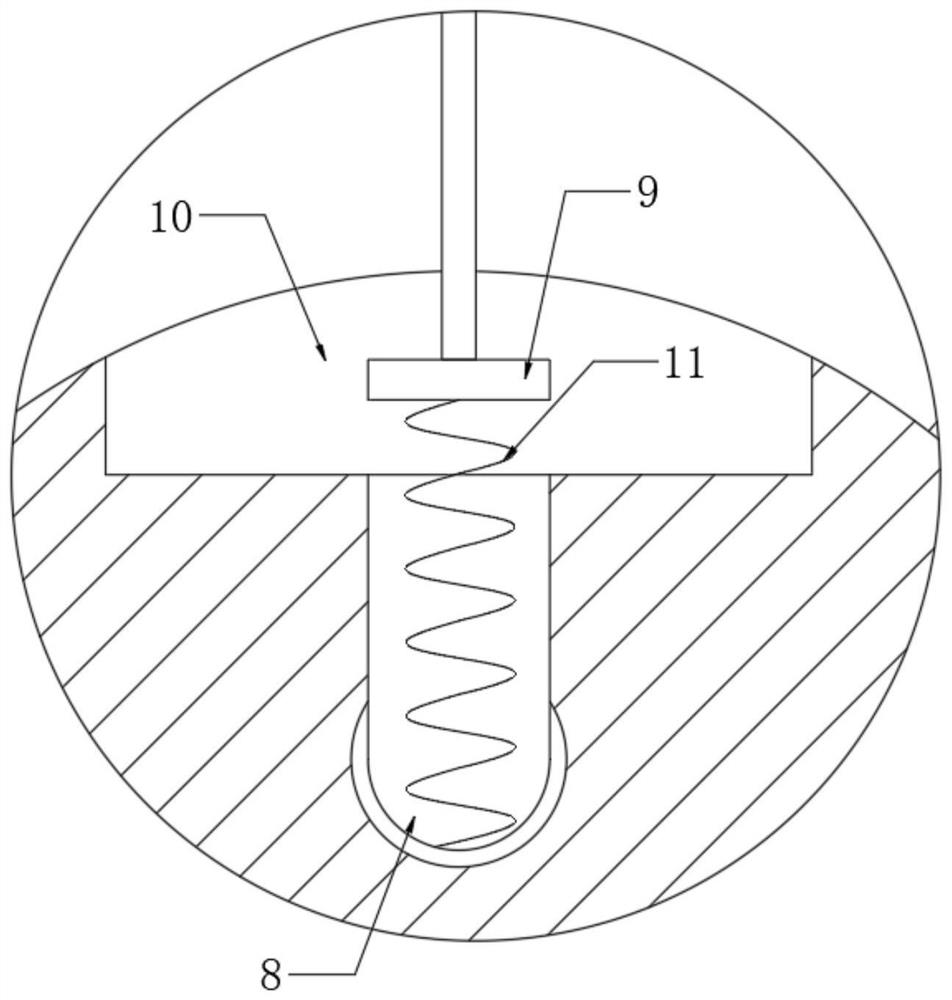
[0023] refer to Figure 1-3 , a sponge city road drainage system, including a drainage channel 2 dug on the subgrade 1, an annular groove 3 is dug under the subgrade 1, and the annular groove 3 and the drainage channel 2 are connected through a diversion channel 21, and the annular groove 3 is slidingly connected with a first baffle 4, and the annular groove 3 is fixedly connected with a second baffle 5, and the first baffle 4 and the second baffle 5 are elastically connected by a first spring 6, and the guide groove 21 A filter screen 211 is embedded in it, an arc-shaped groove 10 is opened on the inner wall of the annular groove 3, a water supply pipe 7 communicating with the annular groove 3 is buried in the roadbed 1, and a sewage discharge pipe communicating with the arc-shaped groove 10 is also embedded in the roadbed 1 The pipe 8 and the arc groove 10 are slidingly connected with a sealing plug 9. It should be noted that after the sealing plug 9 enters the sewage pipe 8...

Embodiment 2

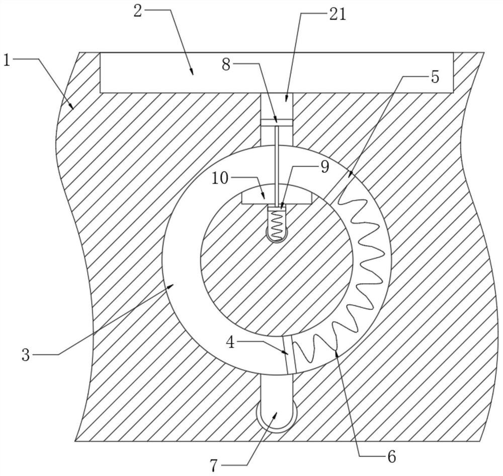
[0026] refer to Figure 4-6 , and the difference from Embodiment 1 is that a storage tank 12 is dug on the subgrade 1, and the storage tank 12 communicates with the diversion tank 21 through the first diversion tank 13, and a scraper is slidably connected in the first diversion tank 13 17. The inner wall of the diversion groove 21 is provided with a second flow diversion groove 14, and a pushing device for pushing the scraper 17 to move is installed in the second flow diversion groove 14.

[0027] The pushing device includes a third spring 15 fixedly connected to the inner wall of the second shunt 14, and the third spring 15 is fixedly connected to the scraper 17, the scraper 17 is made hollow, and an electromagnet 171 is installed in the scraper 17. An iron limiting block 16 is fixedly connected to the inner wall of a splitter groove 13 .

[0028] It should be noted that the iron limit block 16 is set at the notch position of the first splitter groove 13, on the one hand, it...


PUM


Abstract

The invention discloses a sponge city road drainage system. The system comprises a drainage channel dug in a roadbed, an annular groove is dug in the roadbed, the annular groove is communicated with the drainage channel through a flow guide groove, a first baffle is slidably connected in the annular groove, and a second baffle is fixedly connected in the annular groove. The first baffle and the second baffle are elastically connected through a first spring, a filter screen is embedded in the flow guide groove, an arc-shaped groove is formed in the inner wall of the annular groove, and a watersupply pipe communicating with the annular groove is embedded in the roadbed. Rainwater containing a large amount of pollutants in the initial stage is guided into a sewage treatment system through ablow-off pipe, the road is gradually flushed cleanly by the rainwater as time goes by, and cleaner rainwater in the later stage can be directly guided into a designated place through the water supplypipe to be collected, so that the rainwater on the road surface is treated by stages, the rainwater absorption efficiency of a sponge city is guaranteed, and meanwhile, a polluted water source can betreated.

Description

technical field [0001] The invention relates to the relevant technical field of sponge city municipal construction, in particular to a sponge city road drainage system. Background technique [0002] In the construction process of sponge city, the design of drainage system is particularly important, especially for some southern cities with frequent rains, the discharge of road water is very critical. [0003] When building a sponge city, it is often necessary to collect rainwater and discharge it to a designated location when it is used. Since the rainwater on the road flows, it often carries a large amount of road pollutants, and the rainwater needs to be treated by the sewage treatment system first. However, if all the rainwater on the road surface is directly discharged into the sewage treatment system, the pressure on the urban sewage treatment system will be sharply increased, resulting in low efficiency of rainwater drainage on the road surface and causing water accumul...

Claims


Application Information

Patent Timeline
Patent Type & Authority Applications(China)
IPC IPC(8): E03F3/04E01C11/22E03B3/02E03F5/04E03F5/14B01D33/01
CPCB01D33/0158E01C11/224E03B3/02E03F3/046E03F5/0401E03F5/14Y02A20/108
Inventor 陶胜明
Owner 临沂人民公园
Why Eureka
Try Eureka