Multi-stage composite rotational flow and turbulent flow sound wave super-strong viscosity reduction, paraffin control and oil increasing device

A turbulent sound wave, super technology, applied in the field of turbulent sound wave super viscosity reduction, wax prevention and oil increase device, multi-stage composite swirl, can solve the problem of easy blockage of oil pipes, achieve enhanced emulsification effect and improve flow performance Effect

Active Publication Date: 2020-12-18
HUANGSHI BOHUI TECH CO LTD
View PDF13 Cites 8 Cited by
  • Summary
  • Abstract
  • Description
  • Claims
  • Application Information

AI Technical Summary

Problems solved by technology

[0003] The purpose of the present invention is to solve the above-mentioned problem that the oil pipes are easily blocked in the later stage of oil recovery, and provide a multi-stage composite swirling flow, turbulent flow sound wave super-strong viscosity-reducing, wax-proof, and oil-increasing device

Method used


Image

  • Multi-stage composite rotational flow and turbulent flow sound wave super-strong viscosity reduction, paraffin control and oil increasing device
  • Multi-stage composite rotational flow and turbulent flow sound wave super-strong viscosity reduction, paraffin control and oil increasing device
  • Multi-stage composite rotational flow and turbulent flow sound wave super-strong viscosity reduction, paraffin control and oil increasing device

Examples


Embodiment Construction

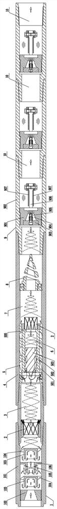
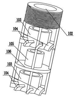
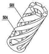
[0034] see Figure 1-6 , the present embodiment includes a tube shell 4, the front end of the tube shell 4 is provided with an oil inlet, and the rear end is provided with an oil outlet. The flow mechanism 5 includes an outer swirl sleeve 501 installed on the inner wall of the tube shell 4. An intermediate spacer 502 is fixedly installed on the inner wall of the outer swirl sleeve 501. The inner swirl column core 503 is installed inside the middle spacer 502. The swirl sleeve 501 and the inner swirl core 503 are respectively provided with an outer spiral oil passage and an inner spiral oil passage, and the middle spacer 502 is used to separate the inner spiral oil passage from the outer spiral oil passage , the tube shell 4 is located inside the oil outlet and is equipped with an atomizing nozzle 8; the tube shell 4 is equipped with a multi-stage turbulence mechanism 1 at the outer end of the oil inlet, and the multi-stage turbulence mechanism 1 and the layered swirl mechanism...


PUM


Abstract

The invention provides a multi-stage composite rotational flow and turbulent flow sound wave super-strong viscosity reduction, paraffin control and oil increasing device. The multi-stage composite rotational flow and turbulent flow sound wave super-strong viscosity reduction, paraffin control and oil increasing device comprises a pipe shell; an oil inlet is formed in the front end of the pipe shell; an oil outlet is formed in the rear end of the pipe shell; a layered rotational flow mechanism is mounted in the position, located behind the oil inlet, in the pipe shell and comprises an outer-layer rotational flow sleeve mounted on the inner wall of the pipe shell; a middle spacer sleeve is fixedly arranged on the inner wall of the outer-layer rotational flow sleeve; an inner-layer rotationalflow column core is arranged in the middle spacer sleeve; the middle spacer sleeve is used for separating an inner-layer oil passage from outer outer-layer oil passage; an atomizing nozzle is arranged in the position, located on the inner side of the oil outlet, in the pipe shell; a multi-stage turbulent flow mechanism is arranged at the outer end of the oil inlet in the pipe shell; a first-stageturbulent flow chamber is formed between the multi-stage turbulent flow mechanism and the layered rotational flow mechanism; a second-stage turbulent flow chamber is formed between the rear end of the middle spacer sleeve and the end part of the inner-layer rotational flow column core; and a third-stage turbulent flow chamber is formed between the layered rotational flow mechanism and the atomizing nozzle. According to the multi-stage composite rotational flow and turbulent flow sound wave super-strong viscosity reduction, paraffin control and oil increasing device, the paraffin control and viscosity reduction effects are greatly improved, the efficiency of an oil well pump is improved, an oil pipe almost cannot be blocked, and the yield of an oil well is increased.

Description

technical field [0001] The invention relates to the field of oil extraction equipment, in particular to a multi-stage compound swirling flow, turbulent flow sound wave super-strong viscosity-reducing, wax-reducing, wax-reducing and oil-increasing device. Background technique [0002] In the later stage of crude oil production, due to the low pressure and insufficient energy of the reservoir, the liquid production gradually decreases. In order to enhance oil recovery, the main components of the production fluid in crude oil production are water, crude oil, petroleum gas escaped from crude oil due to pressure reduction, and a small amount of other substances brought out with water and oil in the formation, of which water accounts for 60% -70% or more. Nowadays, it is mainly to inject high-pressure water from the ground into the underground oil layer or add chemical substances that can drive oil into the water, which is called water flooding or compound flooding. In this way, ...

Claims


Application Information

Patent Timeline
Patent Type & Authority Applications(China)
IPC IPC(8): E21B37/00E21B28/00E21B43/16
CPCE21B37/00E21B28/00E21B43/16
Inventor 李震寰朱丽芬张键郑建新
Owner HUANGSHI BOHUI TECH CO LTD
Why Eureka
Try Eureka