Radial flow type turbo expander structure

A turboexpander and radial flow technology, applied in the field of turbines, can solve the problems of sharp changes in blade height, high rotation speed, and long blade, and achieve the effects of low rotation speed, small blade height changes, and high reliability.

Active Publication Date: 2020-12-18
NO 711 RES INST CHINA SHIPPING HEAVY IND GRP
8 Cites 0 Cited by

AI-Extracted Technical Summary

Problems solved by technology

However, due to the different linear speeds of rotation at different radii, the blades are generally long and twisted, and the reaction rate and speed ratio change rapidly along the blade height, so it cannot always be in the best speed ratio state.
Radial turbines are divided into two categories: centrifugal and centripetal. The shape of the impeller of the centripetal turbine is similar to that of the impeller of the semi-open centrifugal compressor. The blades on the impeller are composed of radial straight ...

Method used

Because there is still a little pressure drop at the inlet and outlet of moving blade 51, in order to further reduce the axial thrust that the rotor is subjected to, optionally, the impeller 4 is provided with a balance hole 45 to reduce the pressure difference between the front and the back of the impeller, thereby reduce axial force.
The bottom of diversion cone 3 links to each other with the top of a plurality of stationary blades 21 (this embodiment adopts the mode of welding connection), and the conical top of diversion cone 3 passes through the central through hole 20 of stationary wheel disc 2 and stretches into into the intake pipe 1. The intake pipe 1, the stationary wheel disc 2 and the diversion cone 3 jointly constitute the intake part of the turboexpander structure. The diversion cone 3 is connected with the static wheel disc 2, which has the advantage that the axial thrust generated by the high-pressure gas at the inlet of the turbo expander structure is borne by the static part, thereby greatly reducing the axial thrust on the rotating shaft 5 and reducing the bearing design. difficulty.
The movable blade of the embodiment of the present invention adopts straight blade, and the top is connected with the movable impeller cover to form a closed impeller, which reduces the loss of sealing leakage; meanwhile, aerodynamic and geometrically compatible, all can be designed at the optimum speed ratio along the blade height , under the action of centrifugal force, it has superior liquid handling capacity, meets the design requirements of stable and reliable turbine, high efficiency and energy saving, and achieves the effect of energy saving and emission reduction.
[0024] The impeller 4 is set outside the rotating shaft 5 and is connected with the rotating shaft 5. In this embodiment, the impeller 4 is connected to one end of the rotating shaft 5 to form a cantilever structure. The connection between the rotating shaft 5 and the central hole 40 of the impeller 4 is in the form of a triangular surface, which has the advantage that the transmission s...

Abstract

A radial flow type turbo expander structure comprises an air intake pipe, a static wheel disc, a flow guide cone, an impeller, a rotating shaft, a movable impeller cover and an exhaust flow guide ring. The air intake pipe is connected with the back face of the static wheel disc, a plurality of static blades arranged at intervals in the circumferential direction are arranged on the front face of the static wheel disc and surround a center through hole of the static wheel disc, and a nozzle is formed by a gap between every two adjacent static blades. The bottom of the flow guide cone is connected with the tops of the multiple static blades; the impeller sleeves outside the rotating shaft and is connected with the rotating shaft; a plurality of moving blades arranged at intervals in the circumferential direction are arranged on the front surface of the impeller; and the movable impeller cover is annular, and the bottom face of the movable impeller cover is connected with the tops of the multiple movable blades. The multiple moving blades surround the multiple nozzles; and the exhaust flow guide ring is arranged around the impeller and is opposite to the static wheel disc, and an annular gap between the exhaust flow guide ring and the static wheel disc forms an exhaust channel. When the radial flow type turbo expander structure works, the flow direction of internal working medium gas is centrifugal runoff, and the radial flow type turbo expander structure is efficient, reliable and compact in structure.

Application Domain

Technology Topic

Image

  • Radial flow type turbo expander structure
  • Radial flow type turbo expander structure
  • Radial flow type turbo expander structure

Examples

  • Experimental program(1)

Example Embodiment

[0020] The present invention will be described in detail below in conjunction with the accompanying drawings and specific embodiments.
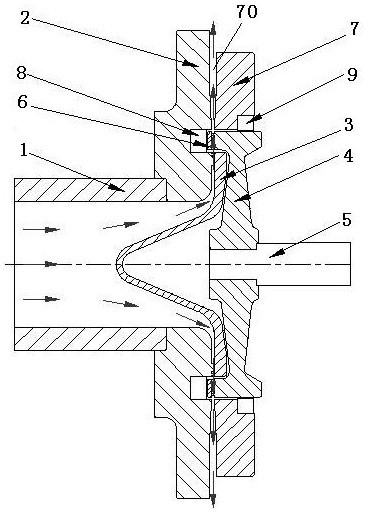
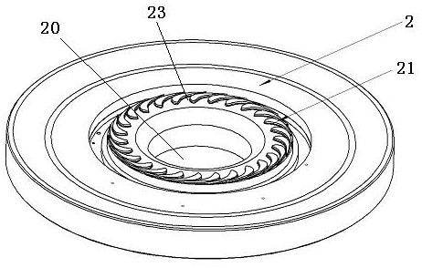
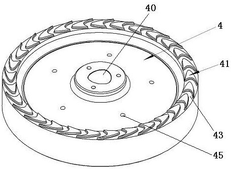
[0021] Please refer to Figure 1 to Figure 3. According to an embodiment of the present invention, a structure of a radial flow turboexpander includes an intake pipe 1, a static wheel disc 2, a guide cone 3, an impeller 4, a rotating shaft 5, a moving impeller cover 6, an exhaust guide ring 7, Moving impeller cover seal 8 and impeller outer peripheral seal 9.
[0022] One end of the intake pipe 1 is connected to the back of the stationary wheel 2, and the connection methods include but not limited to bolt connection, welding and the like. The front of the stationary disc 2 is provided with a plurality of stationary vanes 21 arranged at intervals in the circumferential direction, and the plurality of stationary vanes 21 surround the central through hole 20 of the stationary disc 2, and the gap between each adjacent two stationary vanes 21 is The gap constitutes a nozzle 23, which can decompress and accelerate the gas. The stationary vanes 21 can be integrally formed with the stationary wheel body or can be assembled with individual vanes.
[0023] The bottom of the guide cone 3 is connected to the tops of a plurality of stationary blades 21 (this embodiment adopts the welding connection method), and the cone top of the guide cone 3 passes through the central through hole 20 of the stationary wheel disc 2 and extends into the intake pipe within 1. The intake pipe 1, the stationary wheel disc 2 and the diversion cone 3 jointly constitute the intake part of the turboexpander structure. The diversion cone 3 is connected with the static wheel disc 2, which has the advantage that the axial thrust generated by the high-pressure gas at the inlet of the turbo expander structure is borne by the static part, thereby greatly reducing the axial thrust on the rotating shaft 5 and reducing the bearing design. difficulty.
[0024] The impeller 4 is sheathed outside the rotating shaft 5 and connected with the rotating shaft 5 . In this embodiment, the impeller 4 is connected to one end of the rotating shaft 5 to form a cantilever structure. The connection between the rotating shaft 5 and the central hole 40 of the impeller 4 is in the form of a triangular surface, which has the advantage that the transmission shaft can transmit a large torque in a small size, and at the same time it is easy to disassemble. The front of the impeller 4 is processed with a plurality of moving blades 41 arranged at intervals along the circumference (the meaning of the moving blades is not that the blades themselves can move, but that the moving blades can rotate together with the impeller). The rotor cover 6 is annular, and the bottom surface of the rotor cover 6 is connected to the tops of the plurality of rotor blades 41 . In this embodiment, the bottom surface of the rotor cover 6 is welded to the tops of the plurality of rotor blades 51 . The moving impeller cover 6 and the moving blade 41 together form a closed flow channel, which can reduce the flow loss of gas. Multiple moving blades 41 surround the multiple nozzles 23 , so that the gas output from the nozzles 23 can be discharged from the gap 43 between two adjacent moving blades 41 .
[0025] Since there is still a little pressure drop at the inlet and outlet of the moving blade 51, in order to further reduce the axial thrust on the rotor, the impeller 4 is optionally provided with a balance hole 45 to reduce the pressure difference between the front and back of the impeller, thereby reducing the shaft pressure. Xiangli.
[0026] The exhaust guide ring 7 is arranged around the impeller 4 and is opposite to the stationary disc 2 , and the annular gap between the exhaust guide ring 7 and the stationary disc 4 constitutes an exhaust channel 70 . The impeller 4, the rotating shaft 5 and the moving impeller cover 6 together constitute a shaft system. The static wheel disc 2 and the exhaust guide ring 7 jointly constitute the exhaust part of the turboexpander structure.
[0027] The moving impeller cover seal 8 is installed on the stationary wheel disc 2 and is sealingly matched with the top surface of the moving impeller cover 6 to reduce the gas leakage outside the moving impeller cover 6 . The impeller peripheral seal 9 is installed on the inner peripheral surface of the exhaust guide ring 7, and is sealed with the outer peripheral surface of the impeller 4, so as to reduce the gas leakage from the back of the impeller to the exhaust end.
[0028] The above sealing fit can be a contact seal or a non-contact seal. In this embodiment, the moving impeller cover seal 8 and the impeller peripheral seal 9 are respectively composed of a first non-contact carbon ring seal and a second non-contact carbon ring seal, and the first non-contact carbon ring seal is connected with the stationary wheel The disk 2 is connected by bolts, and the second non-contact carbon ring seal is connected with the exhaust guide ring 7 by bolts. The exhaust guide ring 7 is fixed to the casing of the expander. By setting the seal, the internal leakage of the turbo expander structure can be reduced and the efficiency can be improved.
[0029] The flow process of the working medium inside the turboexpander is as follows: the working medium flows in axially from the intake pipe 1, turns from the axial direction to the radial direction after being turned by the guide cone 3, and flows into the nozzle 23 on the stationary wheel disc 2 for acceleration , and then enter the gap 43 between the moving blades 41 on the impeller 4, push the impeller 4 to rotate, and the gas that has done work enters the exhaust passage 70 formed by the stationary wheel disc 2 and the exhaust guide ring 7, and is discharged from the turbo expander structure discharge. The flow route of the working fluid in the turboexpander structure is as follows: figure 1 indicated by the arrow in .
[0030] The moving blade of the embodiment of the present invention adopts a straight blade, and the top is connected with the moving impeller cover to form a closed impeller, which reduces the loss of sealing leakage; at the same time, aerodynamics and geometry are compatible, and the height along the blade can be designed at the best speed ratio. Under the action of the turbine, it has superior liquid handling capacity, meets the design requirements of stable and reliable turbine, high efficiency and energy saving, and achieves the effect of energy saving and emission reduction.

PUM

no PUM

Description & Claims & Application Information

We can also present the details of the Description, Claims and Application information to help users get a comprehensive understanding of the technical details of the patent, such as background art, summary of invention, brief description of drawings, description of embodiments, and other original content. On the other hand, users can also determine the specific scope of protection of the technology through the list of claims; as well as understand the changes in the life cycle of the technology with the presentation of the patent timeline. Login to view more.

Similar technology patents

Four-shunting speed reducer for crusher

PendingCN114183503AImprove rigidityReduce axial forceToothed gearingsGearing detailsLoad distributionCrusher
Owner:ZHEJIANG EVERGEAR DRIVING MACHINE

Back-up roll bearing for straightening machine

PendingCN113565870AReduce axial forceReduce frictionBall and roller bearingsBearing componentsBackup rollIndustrial engineering
Owner:辽宁德润新材科技有限公司

Water turbine

ActiveCN109139335AReliable structureReduce axial forceHydro energy generationReaction enginesEngineeringPower turbine
Owner:江西省莲花水轮机厂有限公司

Classification and recommendation of technical efficacy words

  • Reduce axial force
  • Improve operational reliability

Vertical Woltmann water meter

InactiveCN102322901AReduce axial forceHigh sensitivityVolume/mass flow by mechanical effectsImpellerEngineering
Owner:TIANJIN JINMIAO WATER METER MFG

Impact drill

ActiveCN101204740AIncrease kinetic energyReduce axial forcePortable drilling machinesDrill bitEngineering
Owner:POSITEC POWER TOOLS (SUZHOU) CO LTD

Pump shaft axial force adaptive adjusting suspended magnetic pump

PendingCN111396322AReduce axial forceReduce frictionSpecific fluid pumpsPump componentsImpellerMorse taper
Owner:江苏威德凯泵业科技有限公司

High-efficiency rzeppa constant velocity universal joint

PendingCN112211915AReduce axial forceReduce feverYielding couplingPhysicsConstant-velocity joint
Owner:WANXIANGQIANCHAO CO LTD +1

Analysis method for optimizing gas turbine overhaul and maintenance scheme

InactiveCN104850904AImprove operational reliabilityOvercome the problem of unreasonable settingsForecastingSystem safetySecurity analysis
Owner:SHANGHAI NENGCE GAS TURBINE CO LTD
Why Eureka
Try Eureka