
Electronic fuel injection engine system and integrated control method thereof

An engine system, motor control technology, applied in the direction of engine components, machines/engines, engine starting, etc., can solve the problems of low starting efficiency, occupying space, inconvenient maintenance, etc., and achieve the effect of improving real-time performance, real-time conversion and control

Active Publication Date: 2020-12-18
昆山为涵电驱动科技有限公司
View PDF12 Cites 0 Cited by
  • Summary
  • Abstract
  • Description
  • Claims
  • Application Information

AI Technical Summary

Problems solved by technology

[0003] In the existing structure, the above starter motor system and power generation system are two completely independent systems, which not only take up a lot of space, but also have a complex structure. At the same time, because the starter motor system is no longer used after the engine is started, the utilization rate is very low. It also has the disadvantages of low starting efficiency, high failure rate, and inconvenient maintenance. People have been looking for a more efficient and simpler starting solution.

Method used


Image

  • Electronic fuel injection engine system and integrated control method thereof
  • Electronic fuel injection engine system and integrated control method thereof
  • Electronic fuel injection engine system and integrated control method thereof

Examples


Embodiment Construction

[0055]Example embodiments will be described more fully below with reference to the accompanying drawings. However, the example embodiments can be implemented in various forms, and should not be construed as being limited to the embodiments set forth herein. These embodiments are provided to make this application more comprehensive and complete, and to fully convey the concept of the example embodiments to those skilled in the art. In the figures, the same reference numerals denote the same or similar parts, and thus their repeated description will be omitted.

[0056]In addition, the described features, structures or characteristics may be combined in one or more embodiments in any suitable manner. In the following description, many specific details are provided to give a sufficient understanding of the embodiments of the present application. However, those skilled in the art will realize that the technical solutions of this application can be practiced without one or more of the speci...


PUM


Abstract

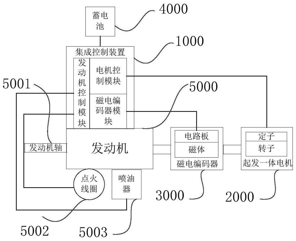
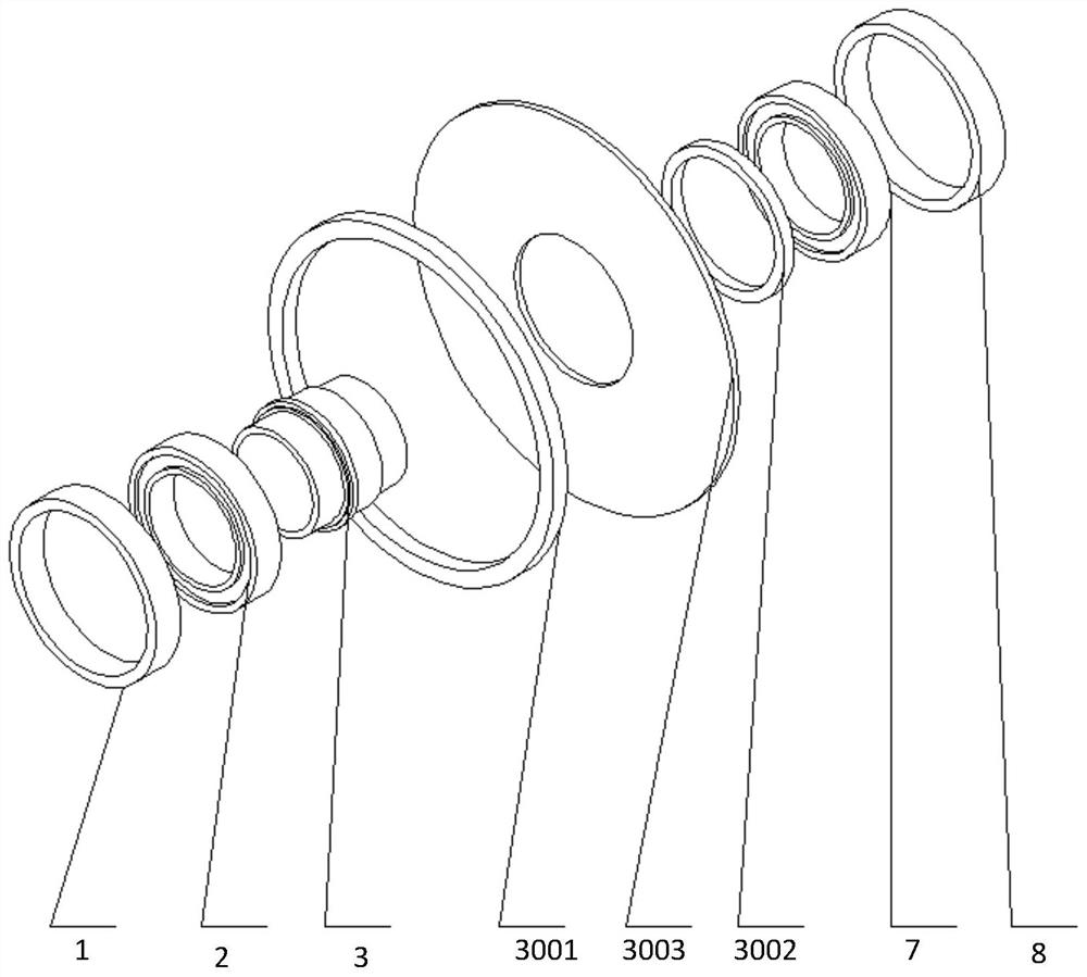
The invention provides an electronic fuel injection engine system and an integrated control method thereof. An electronic fuel injection engine system includes an engine, a starting and generating integrated motor, a magnetoelectric encoder, a first linear Hall sensor, a second linear Hall sensor, a third linear Hall sensor, a fourth linear Hall sensor and an integrated control device. The starting and generating integrated motor is connected with the engine. The magnetoelectric encoder is coaxially arranged with the starting and generating integrated motor and comprises a first multi-pair-pole magnet and a second multi-pair-pole magnet which are coaxially and annularly arranged, wherein the first multi-pair-pole magnet comprises m pairs of magnetic poles, the second multi-pair-pole magnetcomprises n pairs of magnetic poles, and m and n are natural numbers larger than 2 and are relatively prime. The first linear Hall sensor and the second linear Hall sensor are arranged adjacent to the first multi-pair-pole magnet, and the third linear Hall sensor and the fourth linear Hall sensor are arranged adjacent to the second multi-pair-pole magnet. The integrated control device is used forreceiving a signal from the magnetoelectric encoder and controlling the operation of the starting and generating integrated motor. Engine control, motor control and magnetoelectric encoder control are integrated, so that the real-time performance of control is greatly improved.

Description

Technical field[0001]This application relates to the technical field of electric motors, in particular to an electronic fuel injection engine system and an integrated control method thereof.Background technique[0002]The general power plant includes a starter motor system and a generator system. Traditional aircraft and vehicle-mounted engines are started by special starting devices such as hydraulic, gas turbine starters or electric starters. Among them, the electric starter uses a special motor and a variable-speed gearbox to drive the engine. After the start is completed, the starter no longer works, occupying limited space such as aircraft and vehicle systems, increasing the volume and weight.[0003]In the existing structure, the above starter motor system and power generation system are two completely independent systems, which not only take up a lot of space, but also have a complex structure. At the same time, the starter motor system is no longer used after the engine is start...

Claims


Application Information

Patent Timeline
IPC IPC(8): F02B63/04F02N11/04H02K11/215
CPCF02B63/042F02N11/04H02K11/215
Inventor 郝双晖邱津集冯同陈文镥
Owner 昆山为涵电驱动科技有限公司
Learn More