Hydraulic integral integrated valve block

An integrated valve block and integral technology, applied in the direction of fluid pressure actuation device, servo motor, servo motor assembly, etc., can solve the problem of large hydraulic pressure pulsation of hydraulic cylinder, low hydraulic energy transmission efficiency of pneumatic hydraulic hammer, and hammer body system structure. Complex problems, to achieve the effect of improving service life, efficient transmission and utilization, and avoiding direct contact

Inactive Publication Date: 2020-12-18
ZHEJIANG YONGAN CONSTR MASCH CO LTD +1
View PDF9 Cites 1 Cited by
  • Summary
  • Abstract
  • Description
  • Claims
  • Application Information

AI Technical Summary

Problems solved by technology

[0004] The purpose of the present invention is to provide a hydraulic integral integrated valve block to solve the problems of low hydraulic energy transmission efficiency of the pneumatic hydraulic hammer, complex structure of the hammer body system, and large hydraulic pressure pulsation of the hydraulic cylinder, and at the same time provide certain hydraulic components. Protective effects

Method used


Image

  • Hydraulic integral integrated valve block
  • Hydraulic integral integrated valve block
  • Hydraulic integral integrated valve block

Examples


Embodiment Construction

[0026] In order to make the purpose, technical solution and advantages of the present invention clearer, the present invention will be further described below in conjunction with the embodiments described in the accompanying drawings.

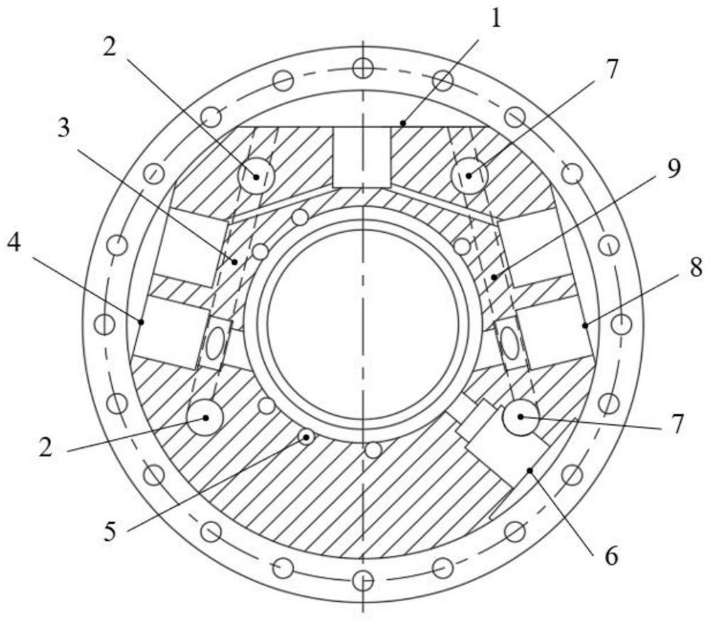
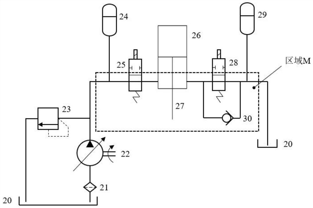
[0027] like figure 1 It is a schematic diagram of the main structure of an embodiment of the present invention. figure 2It is a schematic diagram of the pneumatic hydraulic hammer hydraulic system of the embodiment of the present invention. When working, the piston rod (27) is connected with the hammer core. During the lifting stage, the system supplies high-pressure oil to the hydraulic cylinder (26) through the oil supply control valve (25) from the external hydraulic pump (22) and high-pressure accumulator (24). Under the action of pressure oil, the piston and piston rod (27) drag the hammer core up to the set height, at this time the oil supply control valve (25) is closed; the hammer core will continue to move upward due to inertia, and ...


PUM


Abstract

The invention discloses a hydraulic integral integrated valve block, and belongs to the technical field of hydraulic elements of pneumatic hydraulic hammer systems of engineering machinery. The hydraulic integral integrated valve block is characterized by comprising an oil supply flow passage, high-pressure energy accumulator connectors, oil supply control valve connectors, a hydraulic oil cylinder connector, an oil supplement valve connector, oil return control valve connectors, an oil return flow passage and low-pressure energy accumulator connectors. According to the hydraulic integral integrated valve block, all components of the hydraulic system of a pneumatic hydraulic hammer are integrated into a whole through an oil flow channel and an oil distribution cavity inside, so that the use of connecting pieces is reduced, then the hammer body system is compact in structure, the oil way structure is simplified, on-way loss and local loss of most oil are avoided, and efficient transmission and utilization of hydraulic energy are realized. According to the hydraulic integral integrated valve block, an oil supplementing device is arranged between the oil return flow passage and the oil distribution cavity, then the function of supplementing oil into a hydraulic oil cylinder in the inertia lifting stage of a pile hammer is realized, and thus the problem that the striking energy isreduced due to the fact that too large pressure pulsation is generated in the hydraulic cylinder is avoided. All parts of the hydraulic system are arranged in the hydraulic integral integrated valve block, then direct contact between the parts and the external construction environment is avoided, and thus the service lives of all the parts are indirectly prolonged.

Description

technical field [0001] The invention relates to the hydraulic element technology of a pneumatic hydraulic hammer system in the field of pile machinery of engineering machinery, in particular to a hydraulic integrated valve block. Background technique [0002] With the continuous development of modern construction, a large number of prefabricated concrete pipe piles and steel pipe piles are used in foundation projects such as high-rise buildings, bridges and port terminals, and construction equipment such as diesel piling hammers, static pile machines and hydraulic piling hammers are generally used for piling operations. . Diesel piling hammers have been restricted from being used in central urban areas due to problems such as oil fume emission pollution, high construction noise, and low operating efficiency, which cannot meet social development requirements such as low-carbon environmental protection, green energy conservation, etc. The static pressure pile driver has stric...

Claims


Application Information

Patent Timeline
Patent Type & Authority Applications(China)
IPC IPC(8): F15B1/02F15B11/08F15B13/04
CPCF15B1/02F15B11/08F15B13/04F15B2013/002
Inventor 訚耀保喻展祥郭传新林登
Owner ZHEJIANG YONGAN CONSTR MASCH CO LTD
Why Eureka
Try Eureka