Voltage sag source identification method

A voltage sag source, voltage sag technology, applied in neural learning methods, measurement of electricity, measurement of electrical variables, etc., can solve the problems of difficult parameter setting, affecting the recognition effect, difficult to apply engineering, etc., to achieve simple mathematical principles, avoidance of Feature extraction is difficult and the effect of good robustness

Active Publication Date: 2020-12-18
ELECTRIC POWER RES INST OF GUANGXI POWER GRID CO LTD
View PDF5 Cites 0 Cited by
  • Summary
  • Abstract
  • Description
  • Claims
  • Application Information

AI Technical Summary

Problems solved by technology

[0004]Current methods for voltage sag source identification include feature extraction and pattern recognition; the feature extraction is mainly based on Hilbert-Huang transform, wavelet transform, S-transform and empirical model However, feature extraction is subjective or lacks physical meaning or has redundancy among features, which affects the recognition effect; in addition, wavelet transform has the problem that the basis function and the number of decomposition layers are difficult to determine, while the time window of S transform is fixed , are difficult to apply to engineering; its pattern recognition is mainly based on similarity matching, support vector machines, and fuzzy comprehensive evaluation methods. Although the above pattern recognition methods have realized the identification of voltage sag sources to a certain extent, they may require a large number of samples Training, or there are difficulties in threshold determination, complex models and calculation processes, and difficulty in parameter setting, which have a serious impact on the accuracy and efficiency of voltage sag source identification

Method used


Image

  • Voltage sag source identification method
  • Voltage sag source identification method
  • Voltage sag source identification method

Examples


Embodiment 1

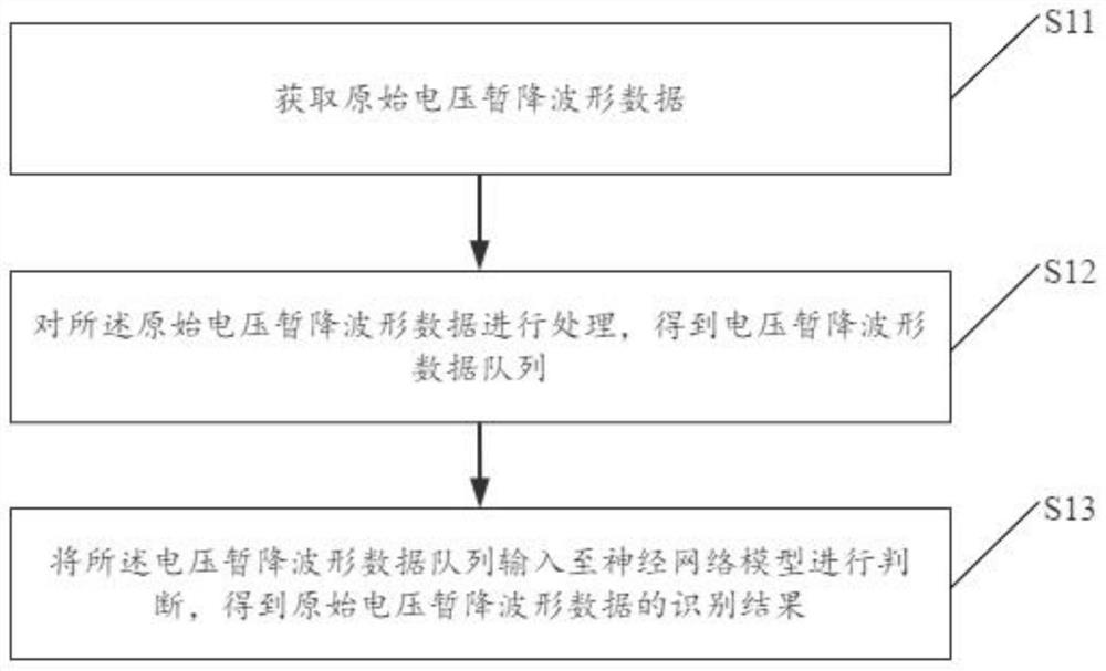
[0043] see figure 1 , figure 1 It is a schematic flowchart of a method for identifying a voltage sag source in an embodiment of the present invention.

[0044] Such as figure 1 As shown, a method for identifying a voltage sag source, the method comprising:

[0045] S11: Obtain original voltage sag waveform data;

[0046] In the specific implementation process of the present invention, obtaining the original voltage sag waveform data includes: installing a voltage sag analyzer on the incoming line side of the sensitive load to monitor the steady-state voltage waveform in real time; when a voltage sag occurs, record the occurrence of the voltage sag The first 5 cycles and the 10 cycles after the voltage sag occurred; upload the voltage sag event and recorded waveform data to the monitoring center.

[0047] S12: Process the original voltage sag waveform data to obtain a voltage sag waveform data queue;

[0048]In the specific implementation process of the present invention, ...

Embodiment 2

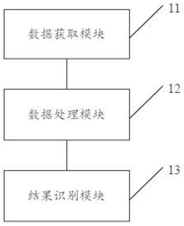
[0095] see figure 2 , figure 2 It is a schematic diagram of the structural composition of the device for voltage sag source identification in the embodiment of the present invention.

[0096] Such as figure 2 As shown, a device for voltage sag source identification, the device includes:

[0097] Data acquisition module 11: for acquiring original voltage sag waveform data;

[0098] Data processing module 12: used to process the original voltage sag waveform data to obtain a voltage sag waveform data queue;

[0099] Result recognition module 13: used to input the voltage sag waveform data queue into the neural network model for judgment, and obtain the recognition result of the original voltage sag waveform data.

[0100] Specifically, for the working principle of the device-related functional modules in the embodiment of the present invention, reference may be made to the relevant description of the method embodiment 1, which will not be repeated here.

[0101] In the i...


PUM


Abstract

The invention discloses a voltage sag source identification method. The method comprises the following steps: acquiring original voltage sag waveform data; processing the original voltage sag waveformdata to obtain a voltage sag waveform data queue; and inputting the voltage sag waveform data queue into a neural network model for judgment to obtain an identification result of the original voltagesag waveform data. In the embodiment of the invention, the specific fault type of the voltage sag source can be quickly and accurately identified, and an important basis is provided for formulating avoltage sag treatment scheme and dividing responsibilities of voltage sag events.

Description

technical field [0001] The invention relates to the technical field of power quality analysis methods, in particular to a method for identifying voltage sag sources. Background technique [0002] With the rapid development of automation, intelligence and digital technology, more and more equipment sensitive to voltage sag is used in the production process; voltage sag is inevitable for the normal operation of the power system, and the effective value of voltage is reduced to 0.1 to Between 0.9p.u and a duration of 0.5 cycles to 1min, the voltage transient phenomenon returns to normal; if the equipment is not operating normally due to voltage sag, it may cause problems in the production process, thereby bringing economic losses to users; therefore , the problem of voltage sag has attracted the attention of users; and the accurate identification of the source of voltage sag can provide an important basis for the formulation of voltage sag control plan and the division of respo...

Claims


Application Information

Patent Timeline
Patent Type & Authority Applications(China)
IPC IPC(8): G01R31/00G01R31/52G01R19/02G06F17/10G06N3/08
CPCG01R31/00G01R31/52G01R19/02G06F17/10G06N3/08
Inventor 陈卫东阮诗雅郭敏金庆忍冯玉斌吴宁姚知洋
Owner ELECTRIC POWER RES INST OF GUANGXI POWER GRID CO LTD
Why Eureka
Try Eureka