Power distribution cabinet wire leading device and power distribution cabinet

A power distribution cabinet lead wire and lead plate technology, which is applied to the substation/distribution device casing, electrical components, busbar/circuit layout, etc. problems, to achieve a wide range of applications, easy to use, to avoid condensation when wet

Inactive Publication Date: 2020-12-18
蚌埠普源电气科技有限公司
View PDF1 Cites 7 Cited by
  • Summary
  • Abstract
  • Description
  • Claims
  • Application Information

AI Technical Summary

Problems solved by technology

[0003] However, there are still obvious defects in its use: 1. When the above-mentioned wire guide is in use, a long section of cable needs to be fixed in the handle of the appliance, but there is no heat dissipation structure in the handle of the appliance , it is easy to cause heat accumulation after long-term use, which makes the temperature of the cable too high and poses a safety hazard; 2. The cable is usually installed in the power distribution cabinet. Abnormal conduction caused by corrosion, the above devices cannot effectively solve this problem

Method used


Image

  • Power distribution cabinet wire leading device and power distribution cabinet
  • Power distribution cabinet wire leading device and power distribution cabinet
  • Power distribution cabinet wire leading device and power distribution cabinet

Examples


Embodiment Construction

[0029] The following will clearly and completely describe the technical solutions in the embodiments of the present invention with reference to the accompanying drawings in the embodiments of the present invention. Obviously, the described embodiments are only some, not all, embodiments of the present invention. Based on the embodiments of the present invention, all other embodiments obtained by persons of ordinary skill in the art without making creative efforts belong to the protection scope of the present invention.

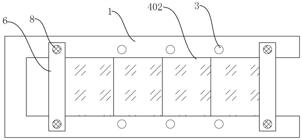
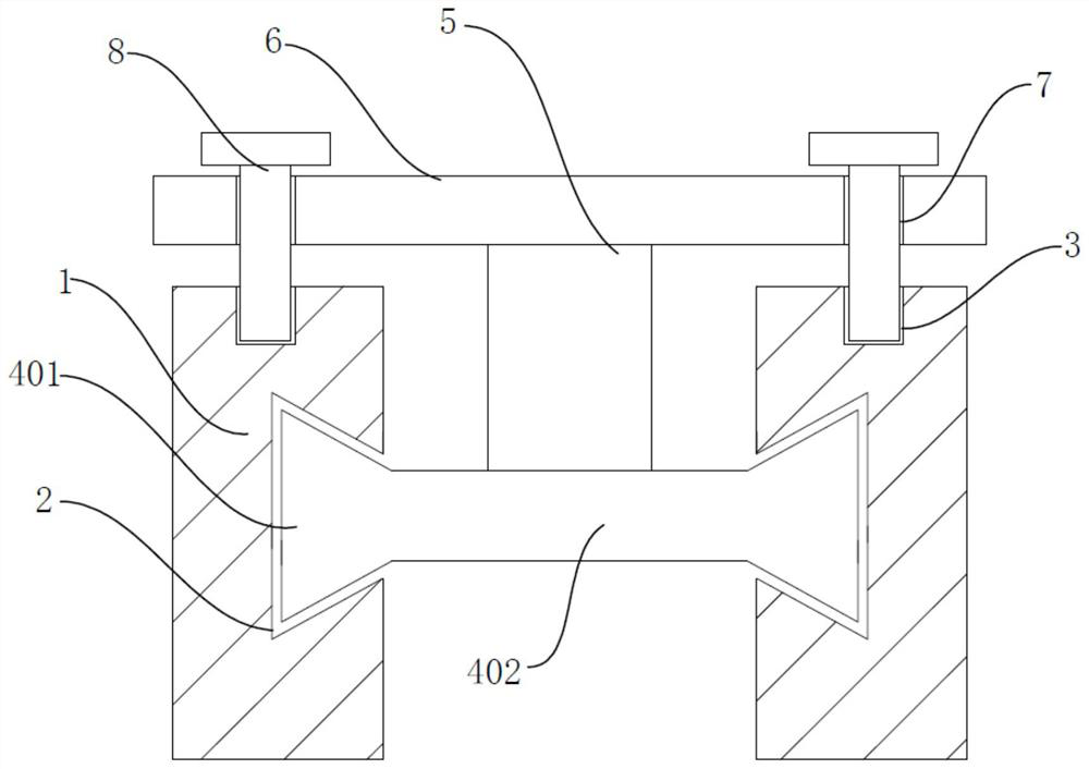
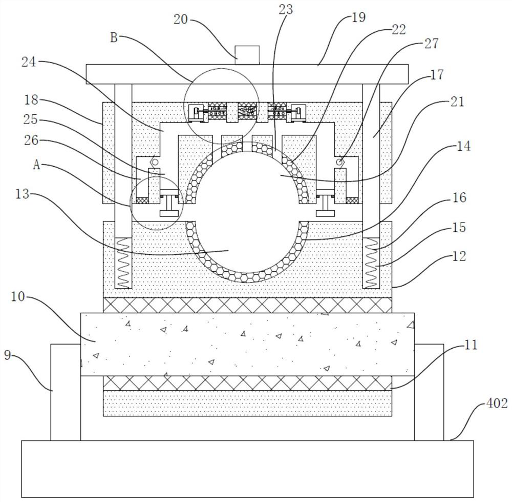
[0030] see Figure 1-5 , the present invention provides a technical solution:

[0031] A lead device for a power distribution cabinet, comprising a U-shaped lead plate 1, on which U-shaped lead plate 1 is symmetrically provided with chute 2, on which U-shaped lead plate 1 is provided with multiple sets of threaded blind grooves 3, in which chute 2 is movable The slider 401, the chute 2 and the slider 401 are all trapezoidal, the slider 401 can move in the chu...


PUM


Abstract

The invention discloses a power distribution cabinet wire leading device and a power distribution cabinet. The power distribution cabinet wire leading device comprises a U-shaped wire leading plate, wherein sliding grooves are symmetrically formed in the U-shaped wire leading plate, and extension plates are fixedly arranged on transverse plates located at the two ends of the U-shaped wire leadingplate; a first circular ring bearing is fixedly arranged on the outer side of the cylindrical shaft and hinged into the lower clamping base. The connecting rod is fixedly arranged in the upper clamping base in a penetrating mode, a heat dissipation hole is formed in the upper rubber pad, a balancing weight is fixedly arranged on the push rod, a plurality of sets of air inlets are formed in the heat dissipation channel in a communicating mode, dustproof nets and isolation nets are arranged in the air inlets, and the drying cavity is filled with a drying agent; and stirring blades are fixedly arranged on the rotating shaft. According to the power distribution cabinet wire leading device and the power distribution cabinet thereof, cables of different thicknesses can be stably clamped, heat dissipation is good, a dustproof net can be automatically cleaned when the power distribution cabinet wire leading device is repeatedly used, and blowing drying and stirring can be conducted on a dryingagent to prevent condensation; therefore, the power distribution cabinet wire leading device is more environmentally friendly and is quite worthy of popularization.

Description

technical field [0001] The invention relates to the technical field of lead-in devices, in particular to a lead-in device for a power distribution cabinet and the power distribution cabinet. Background technique [0002] In the prior art, the application number is "201910041896.0", which is a lead-in device for power distribution cabinets, including the handle of the appliance, the bottom cavity of the wire body, the arc clamp, the hinge ball and the fixing bolt. The center of the surface of the handle of the appliance is The bottom cavity of the wire body is provided at the position, and the two inner walls of one end of the bottom cavity of the wire body are provided with fastening sinking grooves at equal intervals. A fastening spring is installed inside the fastening sinking groove, and the wire on one side of the fastening spring There are arc-shaped clamps inside the cavity at the bottom of the body, arc-shaped clamping sleeves are provided on the outer wall of the han...

Claims


Application Information

Patent Timeline
Patent Type & Authority Applications(China)
IPC IPC(8): H02B1/20H02B1/28H02B1/56B01D53/26B01D46/10
CPCB01D46/10H02B1/20H02B1/202H02B1/28H02B1/565
Inventor 沈文齐陈超
Owner 蚌埠普源电气科技有限公司
Why Eureka
Try Eureka