Aluminum casting solution conveying system

A delivery system and solution technology, applied in the field of aluminum casting, can solve the problems of smaller inner diameter of metal pipes, lower efficiency of molten aluminum, solidification, etc.

Active Publication Date: 2020-12-22
江西晶科铝业有限公司
View PDF17 Cites 0 Cited by
  • Summary
  • Abstract
  • Description
  • Claims
  • Application Information

AI Technical Summary

Problems solved by technology

[0004] 1. When using a high-temperature-resistant metal pipe to transport molten aluminum, since there is no device for heating it on the outer surface of the metal pipe, the temperature outside the metal pipe will be lower than the temperature of the aluminum melting furnace, so that the molten aluminum is in the When flowing from the metal pipe, it is easy to solidify due to the temperature drop, which causes the inner diameter of the metal pipe to gradually become smaller when the aluminum liquid solidifies, reducing the efficiency of conveying the aluminum liquid;
[0005] 2. When using metal pipes to transport aluminum liquid, since the aluminum liquid in the metal pipe is not stirred, it is easy to cause adhesion between the aluminum liquid and the inner wall of the metal pipe; and when the metal pipe completes the transportation of the aluminum liquid, The aluminum liquid that adheres to the inner wall of the metal pipe will gradually solidify on the inner wall of the metal pipe, so that the solidified aluminum adhered to the inner wall of the metal pipe will easily block the aluminum liquid in the flowing state

Method used


Image

  • Aluminum casting solution conveying system
  • Aluminum casting solution conveying system
  • Aluminum casting solution conveying system

Examples


Embodiment Construction

[0032] In order to make the technical means, creative features, goals and effects achieved by the present invention easy to understand, the present invention will be further described below in conjunction with specific illustrations. It should be noted that, in the case of no conflict, the embodiments in the present application and the features in the embodiments can be combined with each other.

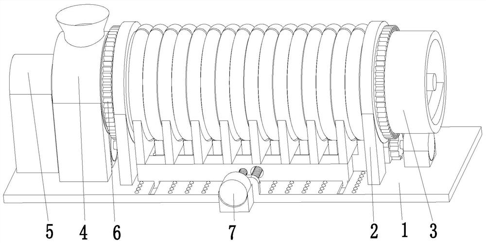
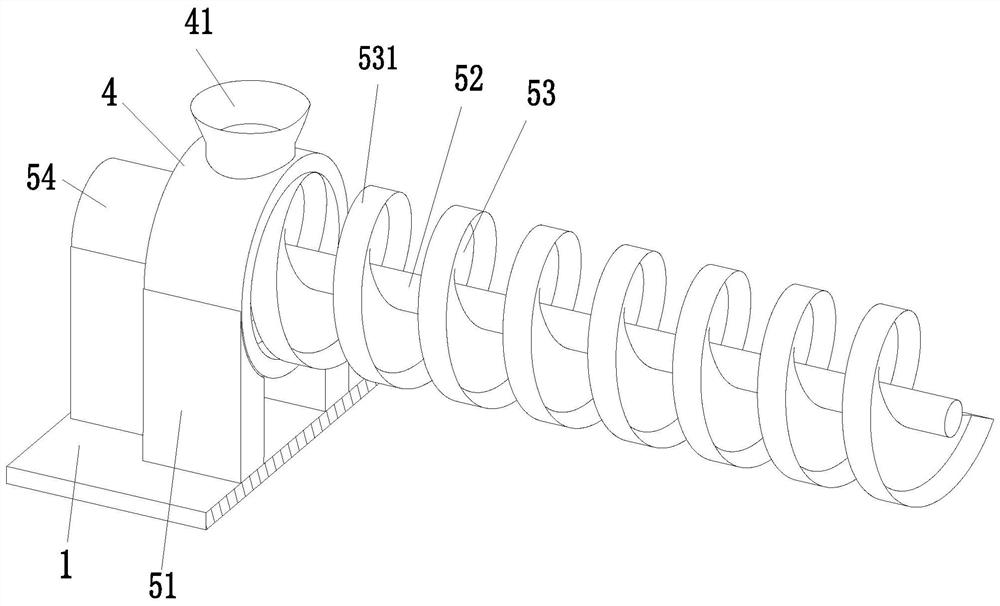
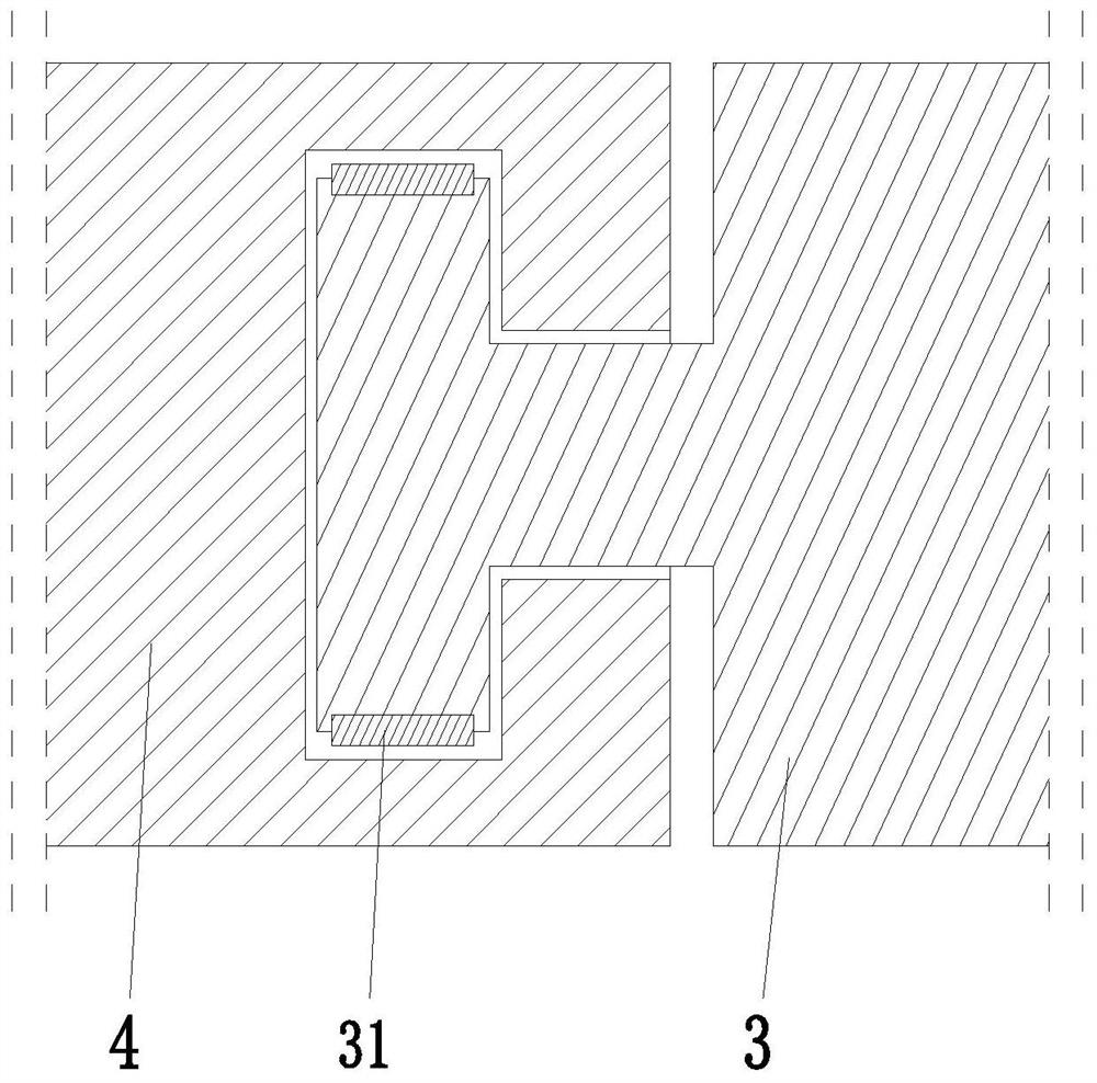
[0033] Such as Figure 1 to Figure 8 As shown, in order to solve the above problems, the present invention provides an aluminum casting solution delivery system, including a base 1, a mounting frame 2, an infusion cylinder 3, a receiving cylinder 4, a stirring mechanism 5, a rotating mechanism 6 and a heating mechanism 7. An installation frame 2 is symmetrically installed on the upper end surface of the base 1. The upper end of the installation frame 2 is a ring structure. The infusion cylinder 3 is installed between the installation frames 2 through rotation and cooperation. The inf...


PUM


Abstract

The invention relates to an aluminum casting solution conveying system. The aluminum casting solution conveying system comprises a base, installing frames, a liquid conveying cylinder, a material receiving cylinder, a stirring mechanism, rotating mechanisms and a heating mechanism, wherein the installing frames are installed on the upper end face of the base in a bilateral symmetry mode, the liquid conveying cylinder is installed between the installing frames in a running fit mode, the material receiving cylinder is installed on the left side of the liquid conveying cylinder in a running fit mode, a material receiving round hole is formed in the upper end of the material receiving cylinder, the stirring mechanism is installed on the inner side of the material receiving cylinder, the rotating mechanisms are installed at the lower end of the liquid conveying cylinder in a bilateral symmetry mode and installed on the upper end face of the base, and the heating mechanism is installed between the rotating mechanisms at the upper end of the base. According to the aluminum casting solution conveying system, the problems that in the prior art, in the process of conveying molten aluminum through a high-temperature-resistant metal pipeline, when the molten aluminum flows in the metal pipeline, solidification is likely to happen due to temperature reduction, due to the fact that the conveyed molten aluminum does not stirred, the molten aluminum is prone to adhering to the metal pipeline are solved.

Description

technical field [0001] The invention relates to the field of aluminum material casting, in particular to an aluminum material casting solution delivery system. Background technique [0002] Aluminum is a silver-white metal, which ranks third in the earth's crust after oxygen and silicon. It is a non-ferrous metal that is second only to steel in terms of output and consumption in the world. Because aluminum is light, it is often used to make cars. , trains, subways, ships, airplanes, rockets, spaceships and other land, sea and air vehicles to reduce their own weight and increase the loading capacity; the recycling of aluminum products is to melt the recycled aluminum products so that the molten aluminum can be reused , and industrial aluminum usually melts the aluminum ingot after the solidified aluminum liquid is melted again, so as to utilize the molten aluminum liquid; therefore, it is particularly important to melt aluminum and transport the molten aluminum liquid in the ...

Claims


Application Information

Patent Timeline
IPC IPC(8): B22D1/00B22D35/00B22D35/06B01F9/08B01F15/00B01F15/06B01F29/64
CPCB22D1/00B22D35/00B22D35/06B01F29/64B01F35/123B01F2035/99B01F35/92
Inventor 王德忠汪尹
Owner 江西晶科铝业有限公司
Why Eureka
Try Eureka