
Casting smelting furnace improved structure facilitating automatic pouring

An automatic pouring and smelting furnace technology, which is applied in the control of molten metal pouring from ladles, casting equipment, casting molten material containers, etc. It can solve the problems that the lifting structure cannot meet the requirements of automatic pouring and the force structure of the lifting mechanism is high.

Inactive Publication Date: 2020-12-22
含山县承力铸造厂
View PDF0 Cites 0 Cited by
  • Summary
  • Abstract
  • Description
  • Claims
  • Application Information

AI Technical Summary

Problems solved by technology

[0003] However, the existing pouring system always uses a relatively complicated lifting mechanism to take out the heavy melting crucible from the smelting furnace before pouring, which has high requirements for the force structure of the lifting mechanism, and the ordinary lifting structure cannot meet the needs of automatic pouring , so it is necessary to change the way of taking out the crucible from the smelting furnace, that is, to propose a new improved structure of the casting smelting furnace

Method used


Image

  • Casting smelting furnace improved structure facilitating automatic pouring
  • Casting smelting furnace improved structure facilitating automatic pouring
  • Casting smelting furnace improved structure facilitating automatic pouring

Examples


Embodiment Construction

[0020] The following will clearly and completely describe the technical solutions in the embodiments of the present invention with reference to the accompanying drawings in the embodiments of the present invention. Obviously, the described embodiments are only some, not all, embodiments of the present invention.

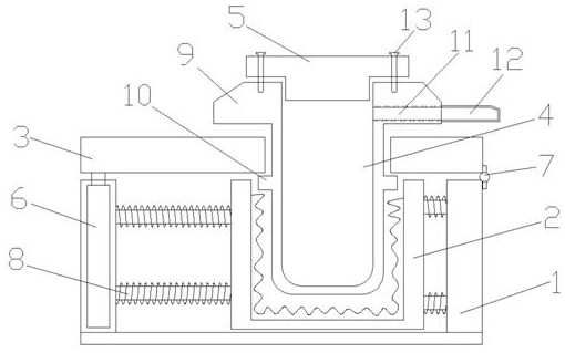
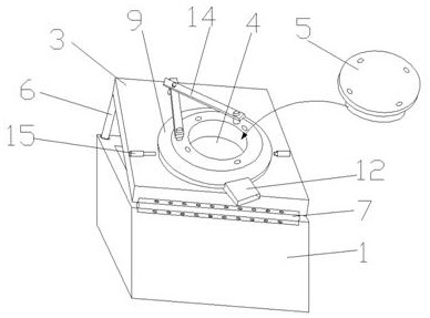
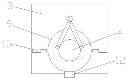
[0021] refer to Figure 1-3 , an improved structure of a casting and smelting furnace that is convenient for automatic pouring, including a heat preservation shell 1, a melting heating cylinder 2 arranged in the heat preservation shell 1, a flip cover plate 3 riveted on the side wall of the heat preservation shell 1, and clamped on the Turn over the melting crucible 4 on the cover plate 3 and the flange cover 5 at the top opening of the melting crucible 4. The heat preservation shell 1 is specifically a square box structure composed of a bottom plate and four side plates. The bottom plate is a solid load-bearing ceramic Material, the side plate is a double-layer holl...


PUM


Abstract

The invention discloses a casting smelting furnace improved structure facilitating automatic pouring. The casting smelting furnace improved structure comprises a heat preservation shell, a melting heating barrel, an overturning cover plate, a melting crucible and a flange cover. A lifting hydraulic rod is arranged in one side plate of the heat preservation shell, and the other side plate of the heat preservation shell is connected with the overturning cover plate through a hinge. The overturning cover plate is clamped between the annular edge and an annular protruding strip of the melting crucible. The annular edge is provided with a discharging channel and a discharging pipe. The flange cover is tightly connected with the annular edge through a screw. A swing rod is riveted to the top face of the annular edge, and the side wall of the annular edge is in contact with a swing hydraulic rod. According to the casting smelting furnace improved structure, the inclination angle of the melting crucible is controlled through the overturning cover plate, and the pouring speed of molten liquid is controlled. The swing rod and the swing hydraulic rod are used for driving the melting crucibleto swing, and the molten liquid in the melting crucible can be sufficiently and evenly shaken. The swing amplitude, the inclination speed and the angle of the melting crucible can be simply controlledthrough control over the lifting hydraulic rod and the swing hydraulic rod, and the casting smelting furnace improved structure is suitable for a casting assembly line for automatic pouring production.

Description

technical field [0001] The invention relates to the technical field of casting and smelting furnaces, in particular to an improved structure of a casting and smelting furnace which is convenient for automatic pouring. Background technique [0002] Throughout the casting process, the role of the gating system is to: control the speed at which the molten metal fills the mold and the time it takes to fill the mold; make the molten metal enter the mold smoothly, avoid turbulence and flushing of the mold; prevent Slag and other inclusions enter the cavity; no gas is involved during pouring, and the principle of sequential solidification should be followed as much as possible when the casting is cooled. [0003] However, the existing pouring system always uses a relatively complicated lifting mechanism to take out the heavy melting crucible from the smelting furnace before pouring, which has high requirements for the force structure of the lifting mechanism, and the ordinary lifti...

Claims


Application Information

Patent Timeline
Patent Type & Authority Applications(China)
IPC IPC(8): B22D37/00B22D41/04B22D1/00B22D41/015
CPCB22D1/00B22D37/00B22D41/015B22D41/04
Inventor 刘加发
Owner 含山县承力铸造厂
Learn More