
Automatic welding equipment for wiring terminal of coil of motor

A coil wiring and automatic welding technology, which is applied to welding equipment, metal processing equipment, and printed circuit assembly of electrical components, can solve the problems of unguaranteed product yield, high labor cost, and defective products.

Pending Publication Date: 2020-12-22
中山明杰自动化科技有限公司
View PDF12 Cites 0 Cited by
  • Summary
  • Abstract
  • Description
  • Claims
  • Application Information

AI Technical Summary

Problems solved by technology

The motor usually consists of a rotor assembly and a stator assembly; the stator assembly needs to weld the pins on the stator assembly and the circuit board sleeved on the pins during the production process. However, the existing welding methods are generally manual. Soldering the pins and the circuit board will result in high labor costs and low production efficiency. At the same time, human factors will also lead to defective products, and the product yield cannot be guaranteed.
[0003] At present, the welding, resistance detection, and visual inspection of solder joints of the motor stator assembly are performed independently by multiple people, which results in high labor costs and low work efficiency

Method used


Image

  • Automatic welding equipment for wiring terminal of coil of motor
  • Automatic welding equipment for wiring terminal of coil of motor
  • Automatic welding equipment for wiring terminal of coil of motor

Examples


Embodiment Construction

[0038] Attached below Figure 1-14 Embodiments of the present invention will be described in detail.

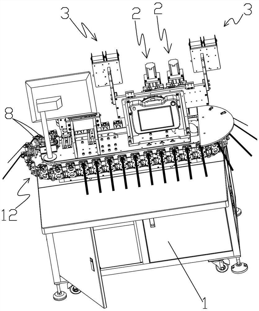
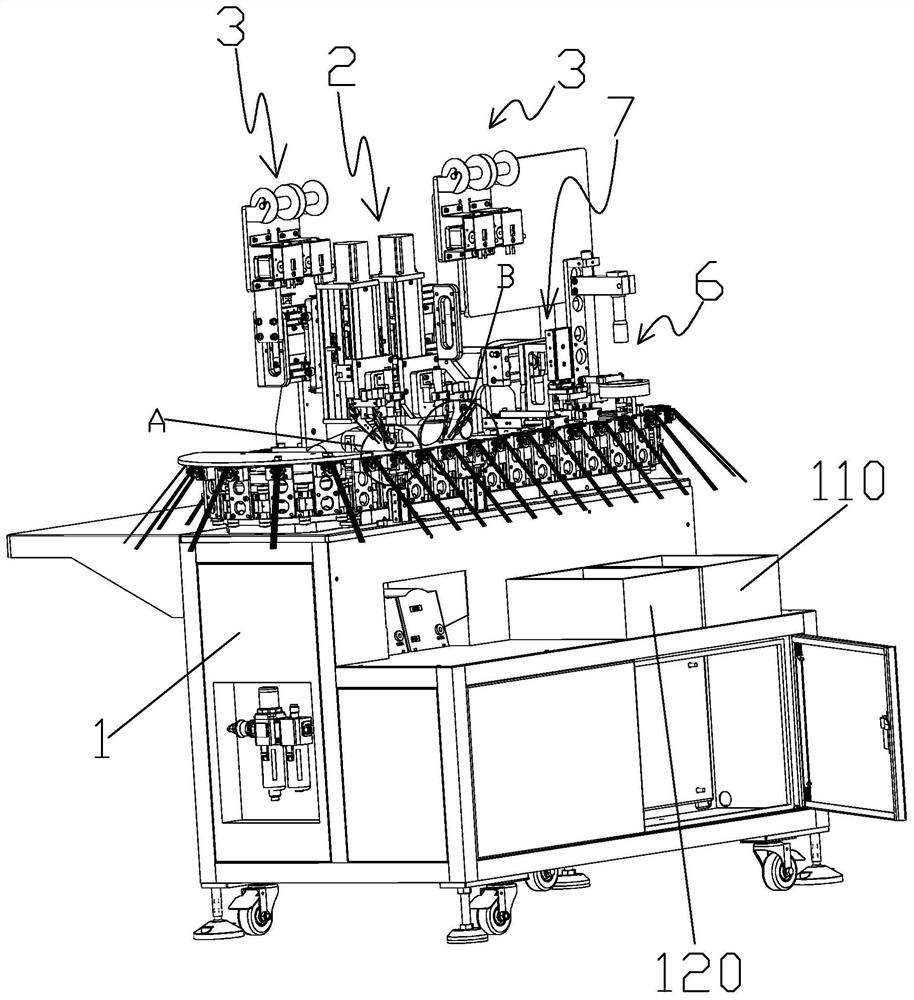
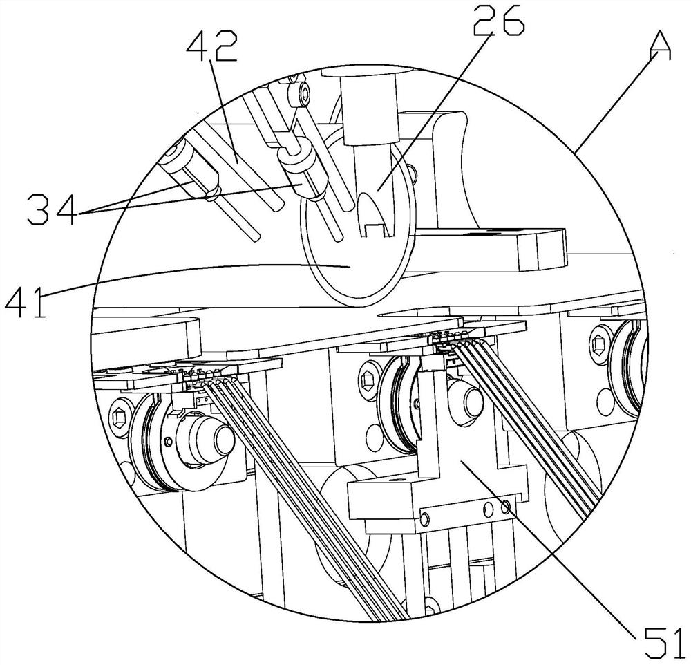
[0039] like Figure 1-14 As shown, an automatic welding equipment for motor coil terminals in the present invention includes a frame 1, a support base 11 is provided on the frame 1, and a rotary table capable of rotating relative to the support base 11 is connected to the support base 11 12. The rotary table 12 is provided with multiple sets of clamping tooling 13 for clamping the coil frame 101 of the stator assembly 100, and the frame 1 is provided with a driving device 14 capable of driving the rotary table 12 to rotate; On the frame 1 and beside the rotary table 12, there is a welding device 2 that can weld the pins 102 on the stator assembly 100 and the circuit board 103 sleeved on the pins 102 together. And be provided with the tin wire feeding device 3 that is used for supplying tin wire to welding device 2 next to welding device 2, be provided with for unloading the...


PUM


Abstract

The invention discloses automatic welding equipment for a wiring terminal of a coil of a motor. The equipment comprises a rack. A supporting seat is arranged on the rack, a rotary worktable capable ofrotating relative to the supporting seat is connected to the supporting seat, a plurality of clamping tools for clamping a coil rack of a stator assembly are arranged on the rotary worktable, and a driving device capable of driving the rotary worktable to rotate is arranged on the rack; a welding device capable of welding a contact pin on the stator assembly and a circuit board arranged on the contact pin in a sleeving manner together is arranged next to the rotary worktable on the rack, a solder wire feeding device for feeding solder wires to the welding device is arranged next to the welding device on the rack, and an unloading device for unloading the welded stator assembly is arranged next to the rotary worktable on the rack. Therefore, the automatic welding equipment can guarantee the yield of products and further has the characteristics of being high in degree of automation, labor cost-saving and high in work efficiency.

Description

【Technical field】 [0001] The invention relates to the field of motors, in particular to automatic welding equipment for motor coil terminals. 【Background technique】 [0002] Motors are common components in the mechanical field and are used in a wide range of applications. The motor usually consists of a rotor assembly and a stator assembly; the stator assembly needs to weld the pins on the stator assembly and the circuit board sleeved on the pins during the production process. However, the existing welding methods are generally manual. Soldering the pins and the circuit board will result in high labor costs and low production efficiency. At the same time, human factors will also lead to defective products, and the yield rate of the products cannot be guaranteed. [0003] At present, the welding, resistance detection, and visual inspection of solder joints of the motor stator assembly are performed independently by multiple people, which results in high labor costs and low w...

Claims


Application Information

Patent Timeline
IPC IPC(8): B23K3/00B23K3/08H05K3/34
CPCB23K3/00B23K3/08H05K3/34B23K3/087
Inventor 梁启进
Owner 中山明杰自动化科技有限公司
Learn More