Precision bearing width grinding device and grinding method thereof

A technology of grinding device and precision bearing, applied in grinding device, grinding driving device, grinding/polishing safety device, etc., can solve the problems of unfavorable grinding, grinding error, short service life of grinding disc, etc., achieve long-term use and improve accuracy , the effect of improving efficiency

Active Publication Date: 2020-12-22
丽水市奥佳自动化有限公司
View PDF14 Cites 7 Cited by
  • Summary
  • Abstract
  • Description
  • Claims
  • Application Information

AI Technical Summary

Problems solved by technology

[0003] 1. When grinding, because there is a star wheel structure on the lower grinding disc, the bearing is installed in the hole inside it for grinding, but the friction of the grinding disc at the bottom is different in the axial direction. The ring and the outer ring are less ground, which will lead to different friction losses in different parts of the grinding disc, which will result in a short service life of the grinding disc, and it is not conducive to grinding, and it is easy to cause grinding errors, which is not good for precision bearings. Allowed;
[0004] 2. Heat will be generated during the grinding process, so the cooling liquid is very important, but in practice, the grinding will produce small powdery abrasive grains, which will cause Grinding small particles while grinding the bearing will not only damage the bearing but also reduce the service life of the grinding disc

Method used


Image

  • Precision bearing width grinding device and grinding method thereof
  • Precision bearing width grinding device and grinding method thereof
  • Precision bearing width grinding device and grinding method thereof

Examples


Embodiment Construction

[0029] The following will clearly and completely describe the technical solutions in the embodiments of the present invention with reference to the accompanying drawings in the embodiments of the present invention. Obviously, the described embodiments are only some, not all, embodiments of the present invention. Based on the embodiments of the present invention, all other embodiments obtained by persons of ordinary skill in the art without making creative efforts belong to the protection scope of the present invention.

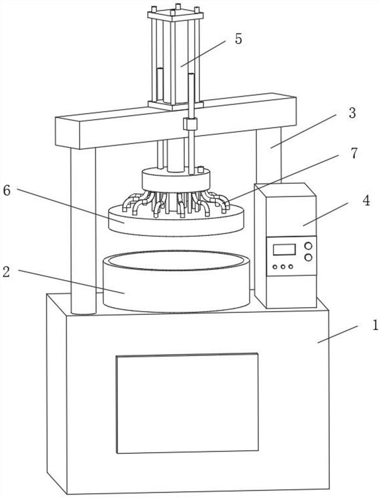
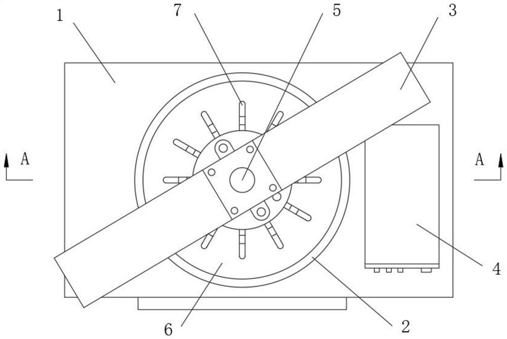
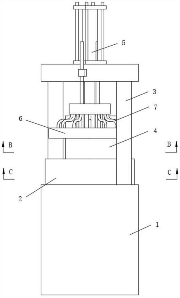
[0030] see Figure 1-12 , a precision bearing width grinding device, comprising a machine base 1, a lower grinding cylinder 2 is fixedly installed on the middle part of the top surface of the machine base 1, a support frame 3 is fixedly installed on the diagonal position of the top surface of the machine base 1, and a support frame 3 is fixedly installed on the top surface of the machine base 1 An electric control box 4 is fixedly installed on one side of the ...


PUM


Abstract

The invention relates to the technical field of machining equipment and discloses a precision bearing width grinding device which comprises a machine base. A supporting frame is fixedly installed at the diagonal position of the top face of the machine base, an upper grinding disc is movably installed at the bottom of the supporting frame, liquid outlet grooves are evenly formed in the bottom of the upper grinding disc, and a lower grinding cylinder is fixedly installed in the middle of the top face of the machine base. Rotary grinding discs are annularly and movably installed at the bottom inthe lower grinding cylinder, planetary wheels externally engaged with a rotary gear column gear are movably installed at the tops of the rotary grinding discs, and a slag discharging device is fixedlyinstalled at the position, located between each rotary grinding disc and a rotary gear column, in the lower grinding cylinder. A grinding disc mounting hole is formed in the position, located at thebottom of the center of each rotary grinding disc, of the lower grinding cylinder, and a liquid collecting cavity is formed in the bottom end of the lower grinding cylinder. The device has the beneficial effects of being high in grinding precision and long in service life by designing the multiple rotary grinding discs and the rotary tooth column for engagement rotation and the slag discharging devices.

Description

technical field [0001] The invention relates to the technical field of mechanical processing equipment, in particular to a precision bearing width grinding device and a grinding method thereof. Background technique [0002] Bearing is a kind of part used a lot in the machinery industry, because it is easy to use and simple in structure, it is very popular, so now there are basically bearings in mechanical equipment, but the requirements for bearings in high-precision industry equipment are high and must be precision Therefore, the grinding of bearings becomes particularly important. The existing grinders use end grinders to grind the width of bearings. The grinding is convenient and has a large range, but there are still some problems: [0003] 1. When grinding, because there is a star wheel structure on the lower grinding disc, the bearing is installed in the hole inside it for grinding, but the friction of the grinding disc at the bottom is different in the axial direction...

Claims


Application Information

Patent Timeline
Patent Type & Authority Applications(China)
IPC IPC(8): B24B5/36B24B55/06B24B47/12B24B55/02B24B41/06B24B37/02B24B37/34B24B37/27
CPCB24B5/36B24B55/06B24B47/12B24B55/02B24B41/067B24B37/02B24B37/34B24B37/27Y02P70/10
Inventor 不公告发明人
Owner 丽水市奥佳自动化有限公司
Why Eureka
Try Eureka