Flexible fiber rope combined stirrup

A technology of flexible fibers and stirrups, which is applied in the field of flexible fiber rope combined stirrups, can solve the problems of labor-intensive, time-consuming and energy-consuming stirrups, and inconvenient construction, so as to reduce labor, increase construction efficiency and save construction time Effect

Pending Publication Date: 2020-12-22
TONGJI UNIV
View PDF0 Cites 2 Cited by
  • Summary
  • Abstract
  • Description
  • Claims
  • Application Information

AI Technical Summary

Problems solved by technology

At present, smooth round steel bars or hot-rolled ribbed steel bars are mainly used as stirrups. In the process of binding steel cages, the binding of stirrups consumes a lot of time and energy, especially the binding of polygonal and closed-shaped stirrups on the inner side of the section is also affected by space constraints. restrictions, the construction is greatly inconvenient, and consumes a lot of labor

Method used


Image

  • Flexible fiber rope combined stirrup
  • Flexible fiber rope combined stirrup
  • Flexible fiber rope combined stirrup

Examples


Embodiment 1

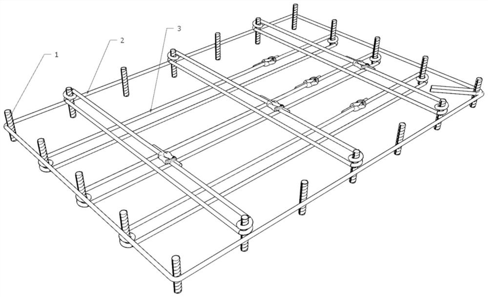
[0042] This embodiment proposes a kind of flexible fiber rope composite stirrup, its structure sees figure 1 with Image 6As shown, it includes the main reinforcement 1 surrounded by a circle or regular polygon, the outer rigid stirrup 2 fixed on the main reinforcement 1, and the inner flexible stirrup 3 connected with all or part of the main reinforcement 1 and restraining it, wherein the main reinforcement 1 and the outer rigid stirrups 2 are bound or welded to form the basic skeleton of the reinforcement cage, and the inner flexible stirrups 3 and the constrained main bars 1 are wound for at least one week, which can effectively reduce the later force and cause the concrete and the inner flexible Slip between stirrups 3. Specifically, the inner flexible stirrup 3 is made of a flexible fiber rope, and the flexible fiber rope is a basalt fiber rope, a carbon fiber rope, or the like.

[0043] In this embodiment, the outer rigid stirrup 2 is fixed to the main reinforcement 1 ...

Embodiment 2

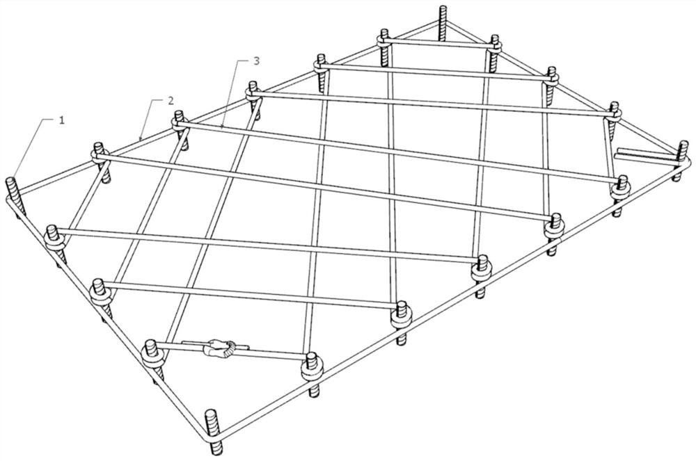
[0045] Compared with Embodiment 1, most of them are the same, except that the number and restraint form of the main reinforcement 1 constrained in this embodiment have changed, specifically: please refer to figure 2 As shown, except for the main reinforcement 1 at the corner, the rest of the main reinforcement 1 are wound and constrained by an inner flexible stirrup 3 to form a cross grid, which reduces the number of knots, thus reducing the internal tension caused by the knots. The sliding of the flexible stirrups 3 and the concrete, and at the same time restraining each main reinforcement 1 can make the pressure arch more flat and increase the area of ​​the restrained concrete.

Embodiment 3

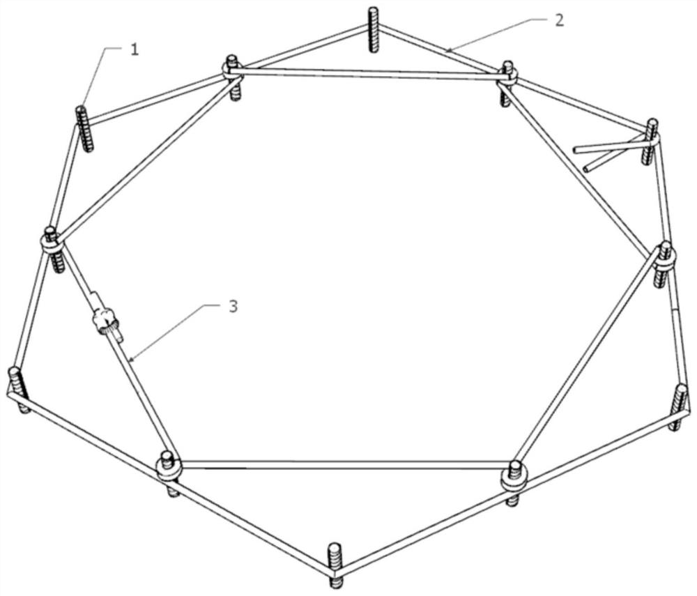
[0047] Compared with Example 1, most of them are the same, except in this example: see image 3 As shown, the cross section of the main reinforcement 1 is arranged in a hexagonal shape, and the end of the outer rigid stirrup 2 is processed into a 135° hook. Except for the main reinforcement 1 at the corner point, an inner flexible stirrup is used between the other main reinforcement 1 3 winding constraints in turn.


PUM


Abstract

The invention relates to a flexible fiber rope combined stirrup. The flexible fiber rope combined stirrup comprises main ribs, outer side rigid stirrups and inner side tightening flexible stirrups, wherein the main ribs are encircled to be circular or regular polygonal, the outer side rigid stirrups are fixed on the main ribs, and the inner side tightening flexible stirrups are connected with allor part of the main ribs and used for restraining the main ribs. Compared with the prior art, the flexible fiber rope combined stirrup is simple in structure and easy and convenient to construct, therequired stirrup mechanical property can be achieved or exceeded, the construction efficiency can be improved, and industrial manufacturing of concrete piers, columns, beams or shear walls and the like is facilitated.

Description

technical field [0001] The invention belongs to the technical field of civil engineering and relates to a flexible fiber rope combined stirrup. Background technique [0002] In reinforced concrete piers, columns, beams, and shear walls, stirrups provide shear strength, erection, reduce the free length of longitudinal bars to prevent buckling, and restrain the core concrete. At present, smooth round steel bars or hot-rolled ribbed steel bars are mainly used as stirrups. In the process of binding steel cages, the binding of stirrups consumes a lot of time and energy, especially the binding of polygonal and closed-shaped stirrups on the inner side of the section is also affected by space constraints. Due to restrictions, the construction is greatly inconvenient and consumes a lot of labor. Contents of the invention [0003] The object of the present invention is to provide a flexible fiber rope composite stirrup, which has a simple structure and convenient construction, and ...

Claims


Application Information

Patent Timeline
Patent Type & Authority Applications(China)
IPC IPC(8): E04C5/16
CPCE04C5/16E04C5/162
Inventor 王志强张鹏辉吕昊吴成峻郝晨宇张霁颜魏红一
Owner TONGJI UNIV
Why Eureka
Try Eureka