
Non-metal expansion joint for solving problem of non-uniform expansion of large-caliber flue

A non-metallic expansion joint technology, applied in the field of thermoelectric facilities, can solve problems such as uneven heating, inconsistent deformation and stretching range, hidden dangers of boiler maintenance costs, etc., and achieve the effect of eliminating cracking and air leakage, and eliminating uneven expansion

Pending Publication Date: 2020-12-22
诸暨市沣泽动力机械有限公司
View PDF0 Cites 0 Cited by
  • Summary
  • Abstract
  • Description
  • Claims
  • Application Information

AI Technical Summary

Problems solved by technology

[0002] A large domestic boiler factory manufactures 200-300MW CFB boilers. The bottom of the furnace is a water-cooled air distribution plate and a primary air chamber. At the same time, it is designed with an oil gun ignition device under the bed. A large-diameter non-metallic expansion joint is designed outside the primary air chamber. The size of the interface is 30 meters long and 4.5 meters wide. When the boiler is started, because the ignition temperature of the oil gun is very high, it is easy to happen that the primary air chamber and the furnace are not uniformly heated in an instant, and the deformation and stretching range caused by thermal expansion are inconsistent, resulting in a primary The overall service life of the air chamber expansion joint can only be maintained for about 2 years, and a large number of weld cracks and air leakage began to occur, and the outer skin was directly damaged, which brought great hidden dangers and maintenance to the long-term safe operation of the boiler. cost

Method used


Image

  • Non-metal expansion joint for solving problem of non-uniform expansion of large-caliber flue
  • Non-metal expansion joint for solving problem of non-uniform expansion of large-caliber flue
  • Non-metal expansion joint for solving problem of non-uniform expansion of large-caliber flue

Examples


Embodiment Construction

[0020] The technical solutions of the present invention will be further specifically described below through the embodiments and in conjunction with the accompanying drawings.

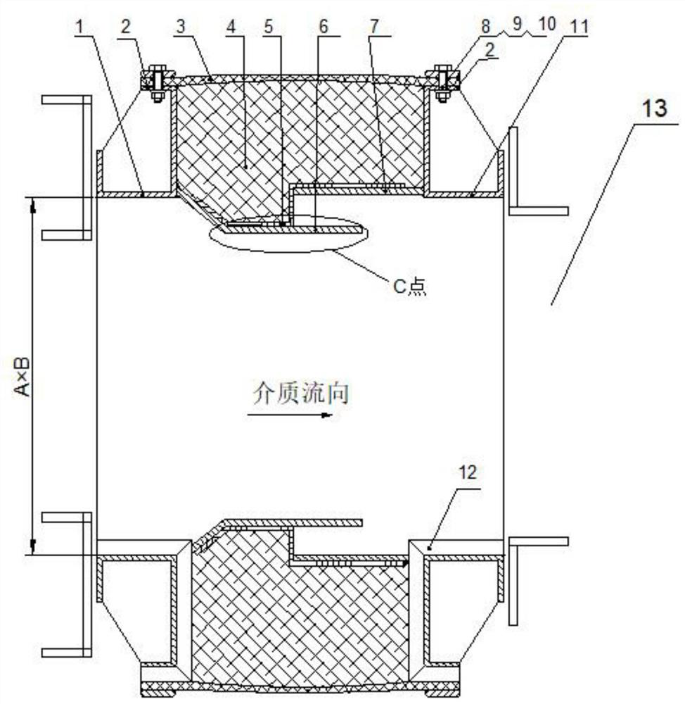
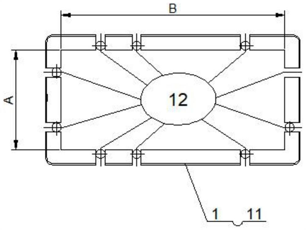
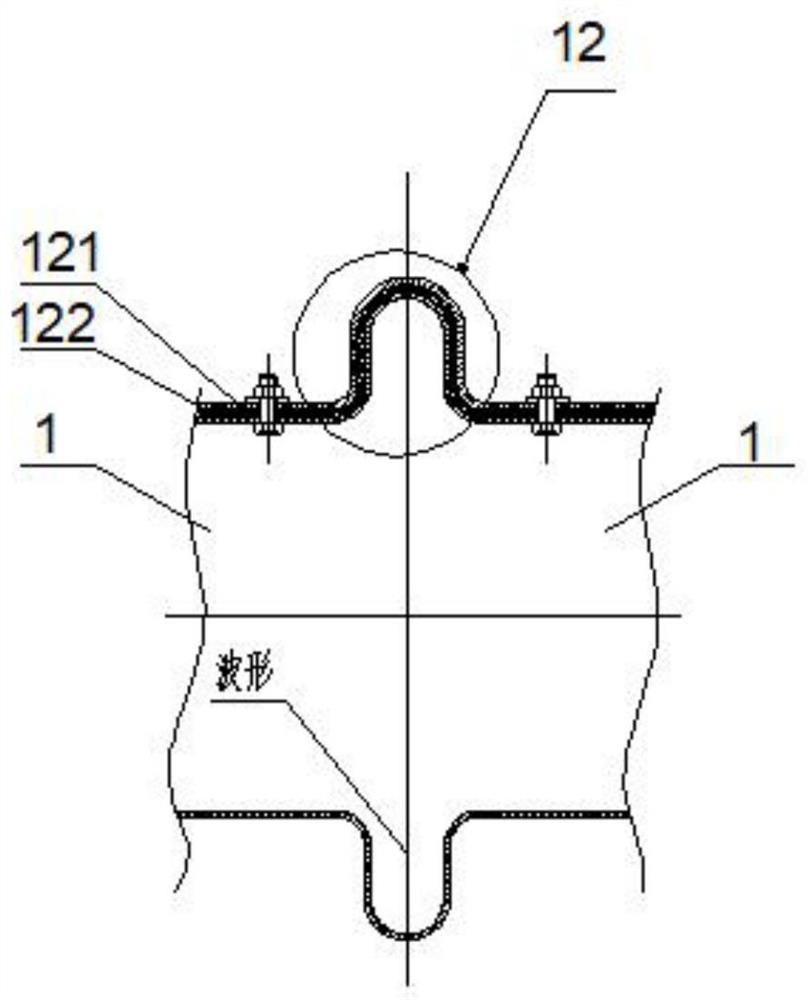
[0021] Such as figure 1 , Figure 6 As shown, a non-metallic expansion joint that solves the uneven expansion of a large-diameter flue. The metal frame 1 and the metal frame 2 11 of the same shape are arranged at both ends of the square non-metallic expansion joint body 13 and arranged symmetrically. The square channel is a high-temperature medium flow channel, and the compression flange 2 that bends outwards at the upper ends of metal frame 1 and metal frame 2 11 is provided with screw holes 101, and the inner side of the lower end of metal frame 1 at the left end is provided with a steel mesh 5 extending to the right , the steel mesh 5 is bent upwards and then stretched to the right, and the lower end of the steel mesh 5 is provided with a lining plate 6, and one end of the lining plate 6 is fixed t...


PUM


Abstract

The invention discloses a non-metal expansion joint for solving the problem of non-uniform expansion of a large-caliber flue. Two metal frames are symmetrically arranged at two ends of a square non-metal expansion joint body, inner lining plates are arranged at the bottoms of the inner sides of the two metal frames respectively, a steel mesh covers the inner lining plates, a heat insulation sleeveis embedded in a formed space, a telescopic body covers the top of the heat insulation sleeve and compresses the heat insulation sleeve, then two ends of the telescopic body are fixedly connected with the two metal frames respectively, the metal frames are formed by splicing sectional type modules, and the sectional type modules are connected through corrugated assemblies. Expansion gaps are formed in the metal frames of the non-metal expansion joint at the intervals of 2000 mm in the circumferential direction, an expansion wave joint is arranged at each gap for absorbing and eliminating non-uniform expansion caused by inconsistent heating of the metal frames of the expansion join, and thus the tension fracture and air leakage conditions of the non-metal expansion joint of a primary air chamber of a boiler are thoroughly eliminated.

Description

technical field [0001] The invention relates to the technical field of thermoelectric facilities, in particular to a non-metallic expansion joint for solving uneven expansion of a large-diameter flue. Background technique [0002] A large domestic boiler factory manufactures 200-300MW CFB boilers. The bottom of the furnace is a water-cooled air distribution plate and a primary air chamber. At the same time, it is designed with an oil gun ignition device under the bed. A large-diameter non-metallic expansion joint is designed outside the primary air chamber. The size of the interface is 30 meters long and 4.5 meters wide. When the boiler is started, because the ignition temperature of the oil gun is very high, it is easy to happen that the primary air chamber and the furnace are not uniformly heated in an instant, and the deformation and stretching range caused by thermal expansion are inconsistent, resulting in a primary The overall service life of the air chamber expansion ...

Claims


Application Information

Patent Timeline
Patent Type & Authority Applications(China)
IPC IPC(8): F16L51/02F16L59/21
CPCF16L51/024F16L51/025F16L59/21
Inventor 陈晓军陈涵瑜俞伟学
Owner 诸暨市沣泽动力机械有限公司
Learn More