Welding image defect identification method and device, storage medium and equipment

A defect identification and welding defect technology, applied in the field of welding image defect identification, can solve the problems of long training time, large manpower and material resources, and achieve the effect of long training time, efficient training and improving the probability of being trained.

Active Publication Date: 2020-12-22
SOUTH CHINA UNIV OF TECH
View PDF5 Cites 16 Cited by
  • Summary
  • Abstract
  • Description
  • Claims
  • Application Information

AI Technical Summary

Problems solved by technology

However, this method needs to obtain a large number of marked welding defect image data, which consumes a lot of manpower and material resources, and the training time is long

Method used


Image

  • Welding image defect identification method and device, storage medium and equipment
  • Welding image defect identification method and device, storage medium and equipment
  • Welding image defect identification method and device, storage medium and equipment

Examples


Embodiment 1

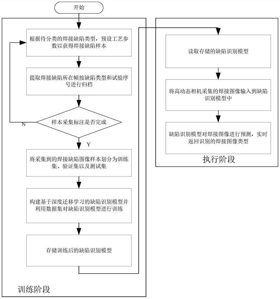
[0058] In this embodiment, a welding image defect recognition method, the process is as follows figure 1 shown, including:

[0059] Obtain the welding image to be identified;

[0060] Inputting the welding image to be identified into the defect recognition model, identifying the welding image through the defect recognition model, and obtaining the type of welding image, thereby determining whether there is a defect in the welding image and determining the type of welding defect if there is a defect; wherein, The defect recognition model described above is a model obtained by training the initial defect recognition model.

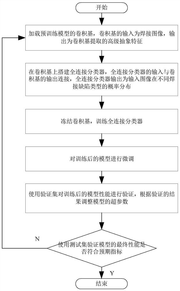
[0061] The training process of the initial defect recognition model refers to the following steps:

[0062] S101. Collect welding image samples of all types of welding defects. Including the following sub-steps:

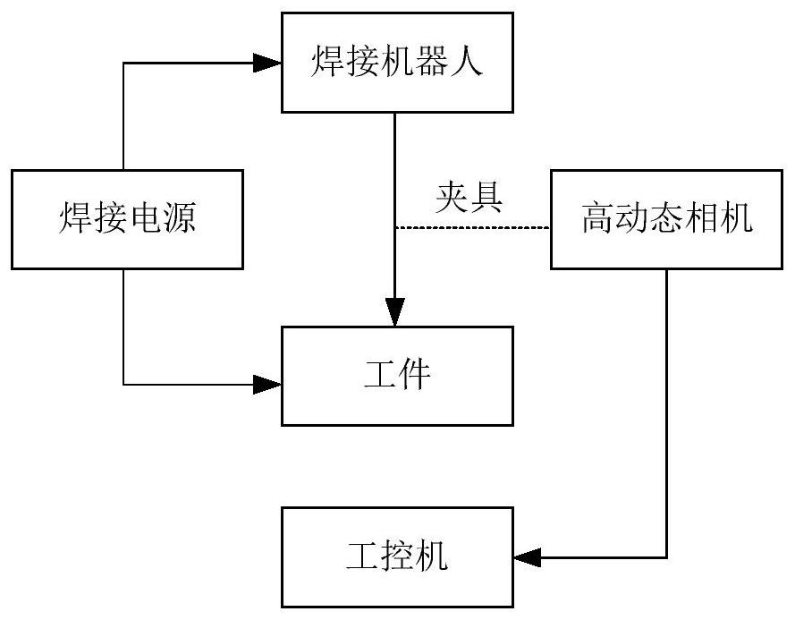
[0063] S1011. According to the types of welding defects to be classified, preset the process parameters of the welding robot and welding power...

Embodiment 2

[0097] In order to realize the welding image defect recognition method described in Embodiment 1, this embodiment provides a welding image defect recognition device, including:

[0098] The data input module is used to obtain the welding image to be identified;

[0099] The data identification module is used to input the welding image to be identified into the defect identification model, identify the welding image through the defect identification model, obtain the type of welding image, and determine whether there is a defect in the welding image and the defect when there is a defect type; wherein, the defect recognition model is a model obtained by training the initial defect recognition model;

[0100] The training process of the initial defect recognition model refers to the following steps:

[0101] S101. Collect welding image samples of all types of welding defects;

[0102] S102. Divide the welding image samples into a training set, a verification set, and a test set...

Embodiment 3

[0106] A storage medium in this embodiment is characterized in that the storage medium stores a computer program, and when the computer program is executed by a processor, the processor executes the welding image defect recognition method described in the first embodiment.


PUM


Abstract

The invention provides a welding image defect recognition method and device, a storage medium and equipment. The method comprises the steps of acquiring a to-be-recognized welding image; inputting theto-be-recognized welding image into a defect recognition model, recognizing the welding image through the defect recognition model to obtain a welding image type, and judging whether the welding image has defects or not and the defect type when the defects exist or not; wherein training processing is carried out on the initial defect recognition model as follows: forming a defect recognition model by combining a convolution basis of a pre-training model with a full-connection classifier; carrying out migration training on the defect recognition model; wherein migration training refers to freezing a convolution basis, training a full-connection classifier, and then finely adjusting a defect recognition model. Based on the combination of deep learning and transfer learning technologies, efficient training of the defect recognition model can be realized under the condition of limited sample number, and the accuracy of welding image defect recognition is improved.

Description

technical field [0001] The present invention relates to the technical field of welding defect recognition, more specifically, to a welding image defect recognition method, device, storage medium and equipment. Background technique [0002] Welding defect identification is an important link to ensure the quality of welding process. Manual welding defect identification is not suitable for continuous high-intensity operations, and the accuracy of manual identification depends on the level of inspectors, which is not conducive to the improvement of welding production efficiency and strict control of welding quality, so the automation of welding defects is promoted Identification is the key to further improving the automation level of welding manufacturing. The current mainstream welding defect recognition relies on digital image processing and complex feature engineering. There are still shortcomings in feature engineering, such as strong subjectivity, complex implementation, a...

Claims


Application Information

Patent Timeline
Patent Type & Authority Applications(China)
IPC IPC(8): G06T7/00G06K9/62G06N3/04G06N3/08
CPCG06T7/0006G06N3/08G06T2207/10004G06N3/045G06F18/214G06F18/2415
Inventor 王振民钟启明陈浩宇张芩吴祥淼
Owner SOUTH CHINA UNIV OF TECH
Why Eureka
Try Eureka