
Distributed photovoltaic energy storage charging system

A distributed photovoltaic and charging system technology, applied in the direction of photovoltaic power generation, solar heating system, power network operating system integration, etc., can solve the problems of low production efficiency, impact, and land occupation of photovoltaic equipment

Pending Publication Date: 2020-12-22
深圳市瑞能时代科技有限公司
View PDF0 Cites 2 Cited by
  • Summary
  • Abstract
  • Description
  • Claims
  • Application Information

AI Technical Summary

Problems solved by technology

[0002] At present, the existing electricity for houses, scenic spots, and commercial uses are generally drawn from the city power. If the city power fails, it will cause power outages in houses, scenic spots, and shops at the same time, which will affect the lives of residents. It will bring a certain degree of inconvenience to the operation of businesses and businesses; at the same time, a large number of electrical equipment will start at the same time during the peak period of electricity consumption, which will bring an excessive burden and impact on the mains, and will directly lead to the paralysis of the mains.
[0003] In order to reduce the burden on the city power and integrate the concept of energy saving and emission reduction, an independent power supply system will be used in a certain range of residential areas, shops or scenic spots to supply power to the electrical equipment in the area, so as to avoid most of the electrical equipment from being directly connected to the city. Electricity, while avoiding large-scale power outages caused by mains failures; however, some of the existing power supply systems still need to use diesel generators for power supply, which has not achieved the effect of emission reduction; or large-scale laying of photovoltaic equipment, resulting in serious land occupation problems, Moreover, the installation location of some photovoltaic equipment is unreasonable, and the sun's rays are blocked by some buildings, resulting in low production efficiency of photovoltaic equipment

Method used


Image

  • Distributed photovoltaic energy storage charging system
  • Distributed photovoltaic energy storage charging system
  • Distributed photovoltaic energy storage charging system

Examples


Embodiment Construction

[0025] Below, the present invention will be further described in conjunction with the accompanying drawings and specific implementation methods. It should be noted that, under the premise of not conflicting, the various embodiments described below or the technical features can be combined arbitrarily to form new embodiments. .

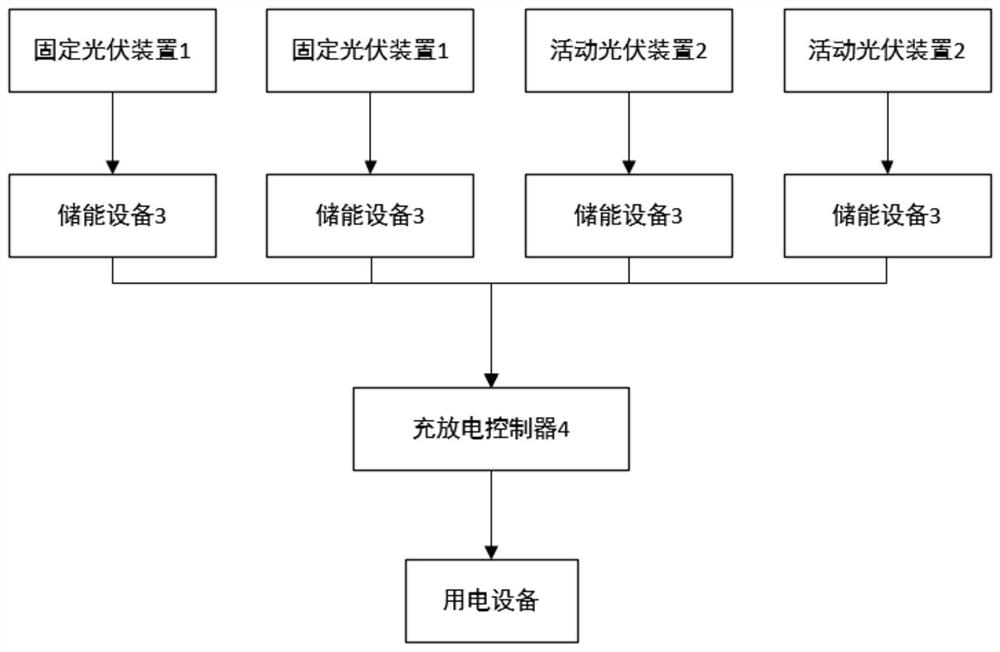
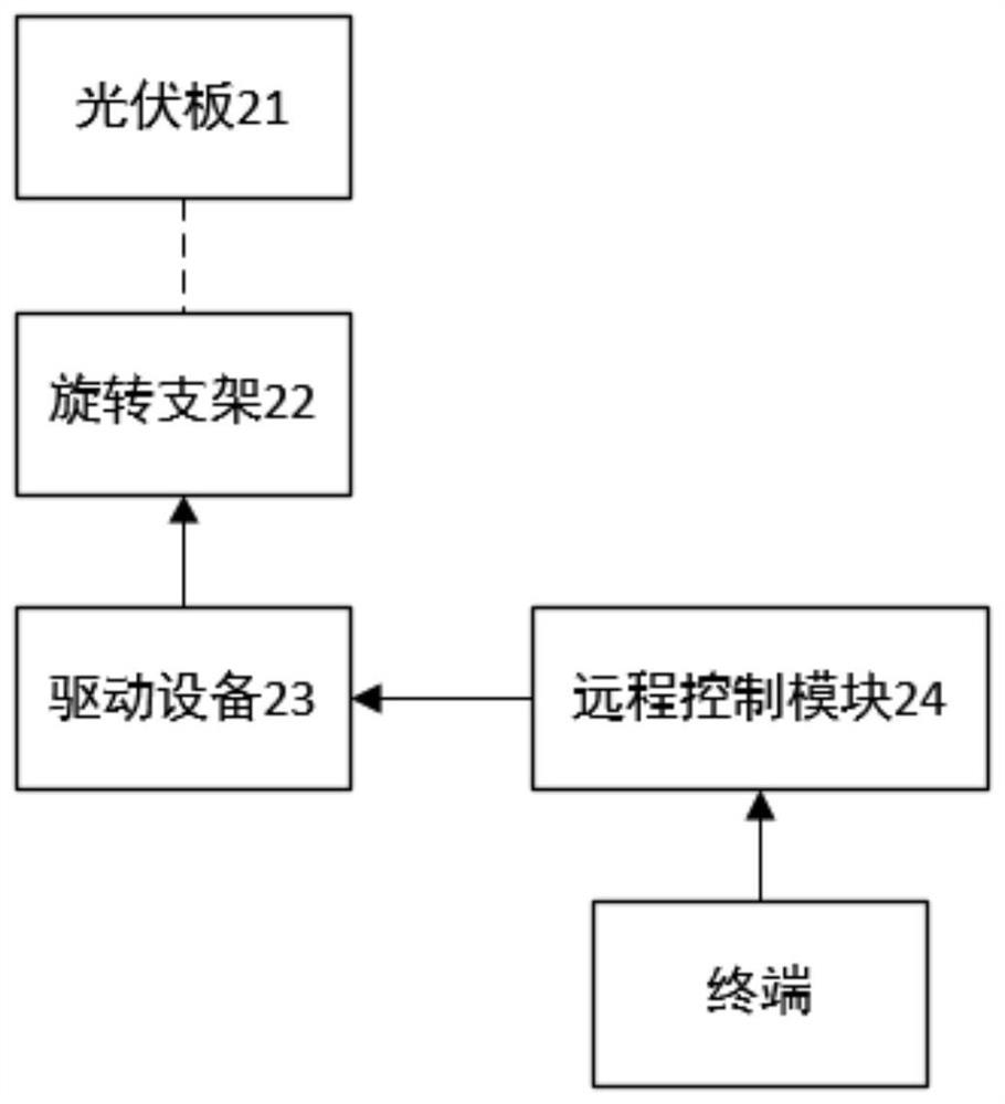
[0026] New energy power generation technology is increasing. New energy can achieve clean, pollution-free and renewable power generation. Solar energy is rich in resources, easy to develop, easy to collect, environmentally friendly and energy-saving, clean and pollution-free, and has large reserves. This embodiment provides a distributed photovoltaic energy storage charging system, which is applied to a building group within a set range, such as a housing range within a certain range, or a scenic area with a certain area, or a shop area of ​​a certain building group. Scenic spots or shops provide distributed power supply to reduce the burden on city po...


PUM


Abstract

The invention discloses a distributed photovoltaic energy storage charging system which is applied to a building group in a set range. The system comprises a plurality of fixed photovoltaic devices and photovoltaic devices with fixed installation angles, which are are respectively arranged at positions where solar rays are always not shielded by buildings in the range of the building group; a plurality of movable photovoltaic devices which are arranged to be photovoltaic devices with rotating angles and are respectively arranged at the positions where solar rays are blocked by buildings in therange of the building group; a charging and discharging controller which is in bidirectional connection with the fixed photovoltaic device and the movable photovoltaic device so as to output the electric energy generated by the fixed photovoltaic device and the movable photovoltaic device to an electric load connected with the charging and discharging controller. The occupied land problem can bereduced, the productivity efficiency of the photovoltaic devices is improved, and energy conservation and emission reduction are achieved.

Description

technical field [0001] The invention relates to the technical field of photovoltaic power generation, in particular to a distributed photovoltaic energy storage and charging system. Background technique [0002] At present, the existing electricity for houses, scenic spots, and commercial uses are generally drawn from the city power. If the city power fails, it will cause power outages in houses, scenic spots, and shops at the same time, which will affect the lives of residents. At the same time, a large number of electrical equipment starts at the same time during the peak period of electricity consumption, which will bring an excessive burden and impact on the mains, and will directly lead to the paralysis of the mains. [0003] In order to reduce the burden on the city power and integrate the concept of energy saving and emission reduction, an independent power supply system will be used in a certain range of residential areas, shops or scenic spots to supply power to the...

Claims


Application Information

Patent Timeline
IPC IPC(8): H02J7/35H02J9/06H02S20/32F24S30/40F24S50/20B60L53/31B60L53/51B60L53/66
CPCB60L53/31B60L53/51B60L53/665F24S30/40F24S50/20H02J7/35H02J9/06H02S20/32Y02B10/10Y02B70/30Y02E10/47Y02E10/50Y02T10/70Y02T10/7072Y02T90/12Y02T90/16Y04S20/20Y02A30/60
Inventor 毛广甫
Owner 深圳市瑞能时代科技有限公司
Learn More