

Electric power steering device
An electric power steering and electric motor technology, which is applied to electric steering mechanisms, power steering mechanisms, electromechanical devices, etc., can solve problems such as short-term immersion in water, and achieve the effect of inhibiting the deterioration of waterproof performance and maintaining the effect of breathing.
- Summary
- Abstract
- Description
- Claims
- Application Information
AI Technical Summary
Problems solved by technology
Method used
Image

Examples
Embodiment approach 1
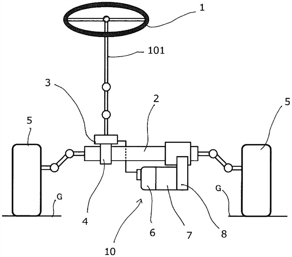
[0033] Hereinafter, the electric power steering device according to Embodiment 1 will be described in detail based on the drawings. figure 1 It is a configuration diagram showing a steering system of a vehicle to which the electric power steering device according to Embodiment 1 is mounted. exist figure 1 Among them, the electric power steering apparatus 10 of Embodiment 1 includes a motor 7 and a control unit 6 that controls the motor 7 . The electric motor 7 and the control unit 6 are axially arranged side by side on the same axis, and axial end portions opposite to each other are joined together to be integrated. The electric power steering device 10 is attached to the pinion unit 8 such that the extending direction of its axis is parallel to the extending direction of the axis of the rack shaft unit 2 of the vehicle.
[0034] The torque sensor 3 is provided on the steering column surrounding the steering shaft 101 , detects the steering torque applied to the steering sha...
Embodiment approach 2
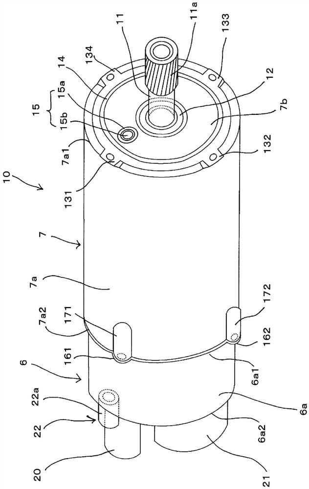
[0060] Next, an electric power steering system according to Embodiment 2 will be described. The electric power steering system according to Embodiment 2 includes: a first breathing device as a motor side breathing device and a second breathing device as a control unit side breathing device, and the breathing function of the second breathing device is set to be higher than that of the first breathing device. High performance. Other structures and operations are the same as those of the electric power steering device in the first embodiment.
[0061] When comparing the above-mentioned first breathing apparatus 15 and the second breathing apparatus 22, there is a big difference in the configured external environments. That is, the ventilation path through which the first breathing device 15 communicates communicates from the inside of the electric power steering device 10 to the outside through the gear unit 8 and the rack shaft unit 2 . On the other hand, the ventilation path ...
Embodiment approach 3
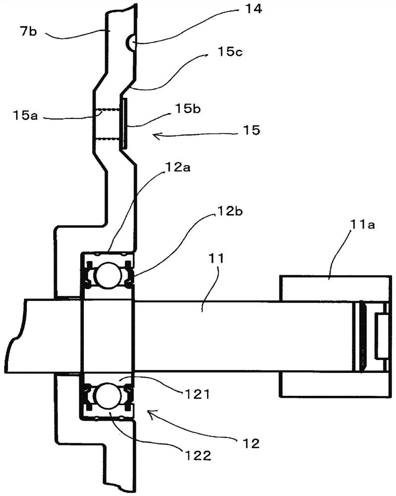
[0066] Next, an electric power steering system according to Embodiment 3 will be described. Figure 5 It is a partial sectional view of the electric power steering device according to the third embodiment. exist Figure 5 Among them, an oil seal portion 18 is attached between the output shaft 11 and the bearing mounting portion 7b1 of the housing wall portion 7b on the side surface on the opposite side to the motor that does not include the waterproof support bearing 12 . The oil seal 18 is composed of, for example, a seal lip 18a made of fluororesin, an outer peripheral eyelet 18b, and an inner peripheral eyelet 18c. The outer peripheral portion of the seal lip 18a is sandwiched between the outer peripheral eyelet 18b and the inner peripheral eyelet 18c. The inner peripheral surface of the seal lip 18a is in close contact with and slides on the outer peripheral surface of the output shaft 11 . According to the structure as described above, the waterproof function of the per...
PUM
 Abstract
Description
Claims
Application Information