
Feeding system of turnover type vibration mill

A technology of vibrating mill and feeding system, applied in solid separation, sieve, grid, etc., can solve the problems of increasing the burden of post-processing, no raw material crushing and screening, etc., to improve the filtering effect, improve the crushing effect, and easy to operate. Effect

Active Publication Date: 2020-12-25
深圳市重力东科电子设备有限公司
View PDF10 Cites 3 Cited by
  • Summary
  • Abstract
  • Description
  • Claims
  • Application Information

AI Technical Summary

Problems solved by technology

[0004] The purpose of the present invention is to solve the problem that the existing feeding device is simply a funnel mouth, does not carry out preliminary crushing and screening of raw materials, and increases the burden of post-processing, and proposes a flip-type vibratory mill. Feeding system

Method used


Image

  • Feeding system of turnover type vibration mill
  • Feeding system of turnover type vibration mill
  • Feeding system of turnover type vibration mill

Examples


Embodiment 1

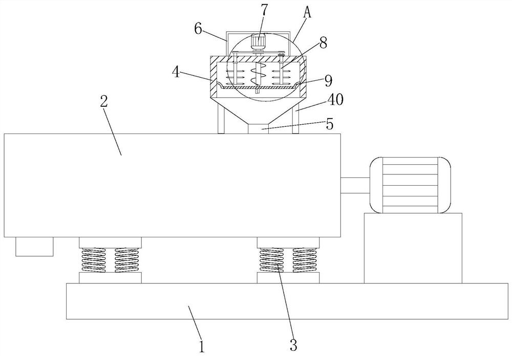
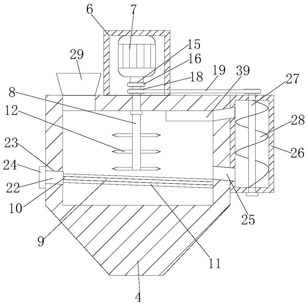
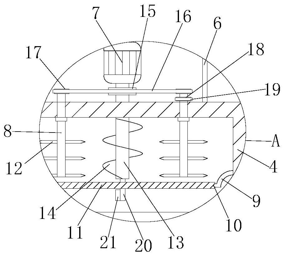
[0030] refer to Figure 1-5 , a feeding system for an overturning vibratory mill, comprising a chassis 1, a buffer structure 3 is arranged on the top of the chassis 1, an overturning vibrating mill 2 is arranged on the top of the buffering structure 3, and the top of the overturning vibrating mill 2 is fixedly connected There is an upper material cylinder 4, the same upper material tube 5 is connected between the bottom of the upper material cylinder 4 and the flipping vibratory mill 2, and two curved elastic rods 9 are fixedly installed on the inner walls of both sides of the upper material cylinder 4 The same filter plate 11 is slidingly connected between the two arc-shaped elastic rods 9, the filter plate 11 is arranged obliquely, the top of the upper material cylinder 4 is fixedly connected with the protective shell 6, and the top inner wall of the protective shell 6 is fixedly connected with the motor 7. A cylindrical rod 13 is fixedly installed on the output shaft of the...

Embodiment 2

[0041] refer to Figure 1-5 , a feeding system for an overturning vibratory mill, comprising a chassis 1, a buffer structure 3 is provided on the top of the chassis 1, an overturning vibrating mill 2 is arranged on the top of the buffering structure 3, and the top of the overturning vibrating mill 2 is passed through a screw The upper material cylinder 4 is fixedly connected, and the same upper material tube 5 is connected between the bottom of the upper material cylinder 4 and the flip-type vibratory mill 2, and two arcs are fixedly installed on the inner walls of both sides of the upper material cylinder 4 by welding. Shaped elastic rod 9, the same filter plate 11 is slidably connected between the two arc-shaped elastic rods 9, the filter plate 11 is arranged obliquely, the top of the upper barrel 4 is fixedly connected with the protective shell 6 by screws, and the top of the protective shell 6 The inner wall is fixedly connected with a motor 7 by screws, and a cylindrical ...


PUM


Abstract

The invention belongs to the technical field of feeding of vibration mills, particularly relates to a feeding system of a turnover type vibration mill, and aims at solving the problems that an existing feeding device is only provided with a funnel opening, raw materials are not subjected to primary smashing, screening and other treatments, and the burden of later-period machining is increased. Through the proposed scheme, the feeding system comprises a chassis, a buffering structure is arranged at the top of the chassis, a turnover type vibration mill is arranged at the top of the buffering structure, a feeding barrel is fixedly connected to the top of the turnover type vibration mill, the bottom of the feeding barrel and the turnover type vibration mill are connected through a same feeding pipe, two arc-shaped elastic rods are fixedly installed on the inner walls of the two sides of the feeding barrel respectively, a same filter plate is slidably connected between the two arc-shaped elastic rods, the filter plate is obliquely arranged, a protective shell is fixedly connected to the top of the feeding barrel, and a motor is fixedly connected to the inner wall of the top of the protective shell. The feeding system is convenient to operate, raw materials can be subjected to primary crushing, screening and other treatments, and the burden of later-period machining is reduced.

Description

technical field [0001] The invention belongs to the technical field of feeding of vibratory mills, in particular to a feeding system of an overturning vibratory mill. Background technique [0002] Existing vibration mills can be divided into continuous mills and discontinuous mills according to their working methods. Continuous mills are suitable for large-scale, single-species production of powders with an average particle size greater than 200 mesh, while discontinuous mills are suitable for medium (small) batches of multi-species powders with an average particle size of less than 100 mesh and greater than 0.3 microns The production of intermittent vibratory mills in the prior art has problems in use such as few varieties and complex structures. In addition, the intermittent vibratory mills of the prior art are mostly provided with feed inlets and outlets on the grinding cylinder. The disadvantage of the material port in use is that during the grinding process of the grin...

Claims


Application Information

Patent Timeline
IPC IPC(8): B02C23/02B02C18/10B02C23/12B02C18/24B02C19/16B07B1/34B07B1/42
CPCB02C18/10B02C18/24B02C19/16B02C23/02B02C23/12B07B1/343B07B1/42
Inventor 谢森涛
Owner 深圳市重力东科电子设备有限公司
Features
  • Generate Ideas
  • Intellectual Property
  • Life Sciences
  • Materials
  • Tech Scout
  • Unparalleled Data Quality
  • Higher Quality Content
  • 60% Fewer Hallucinations
Learn More