Corn particle screening machine
A technology of corn granules and screening machines, which is applied in the field of screening machines, can solve the problems of affecting the environment and making it difficult to ensure the uniformity of the same group of granules, and achieve the effect of promoting uniformity, promoting granules, and ensuring work quality
- Summary
- Abstract
- Description
- Claims
- Application Information
AI Technical Summary
Problems solved by technology
Method used
Image
Examples
Embodiment 1
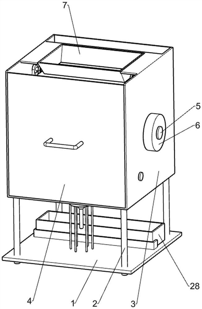
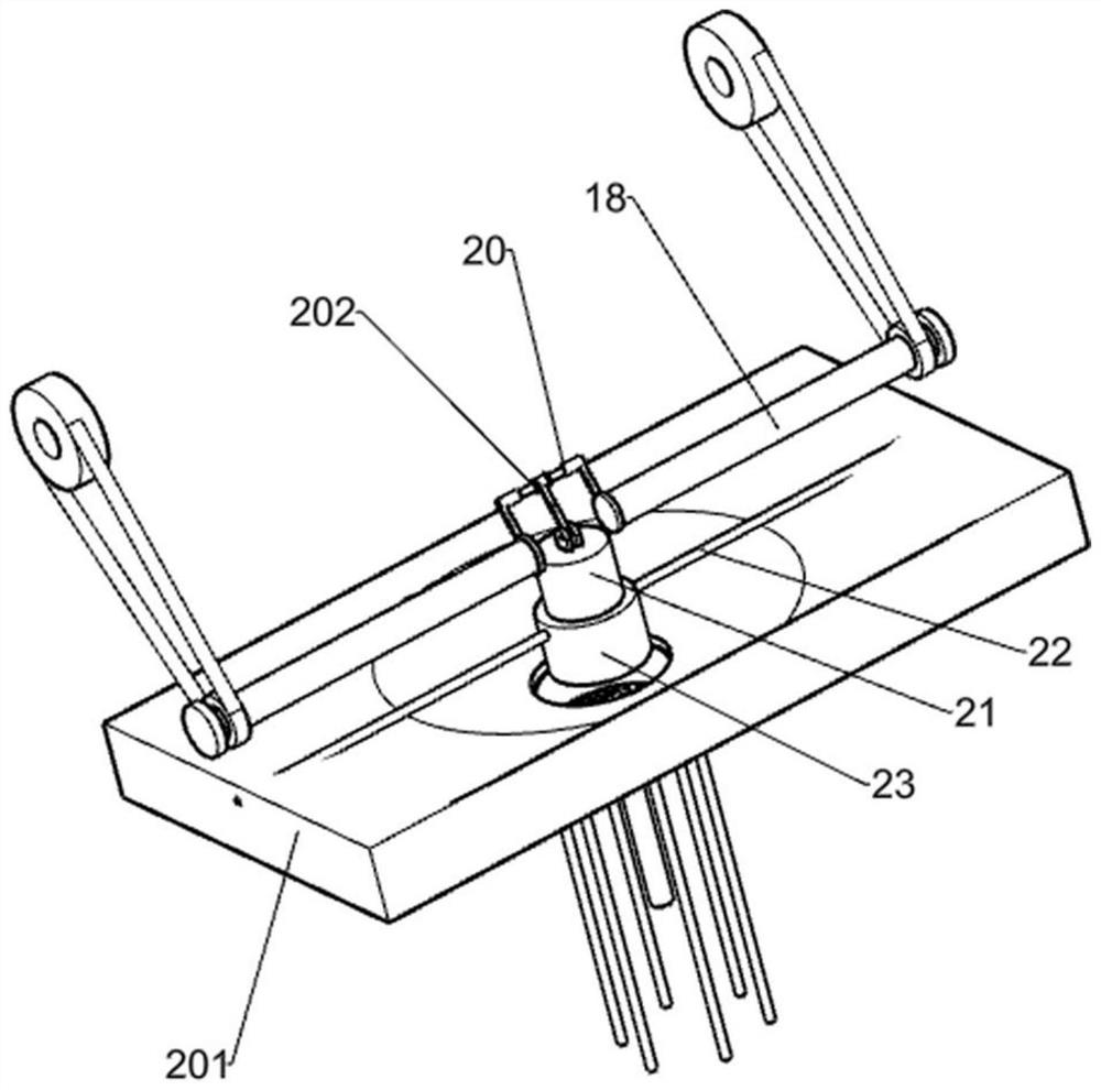
[0021] A corn grain screening machine, such as figure 1 As shown, it includes a bottom plate 1, a support column, a working box 3, a box cover 4, a shaft 5, a pulley 6, a storage tank 28, a feeding mechanism, a screening mechanism and a stamping mechanism, and four support columns 2 arrays The form is installed on the upper part of the bottom plate 1, the upper end of the supporting column 2 is fixedly connected with the work box 3, the front part of the work box 3 is hinged with a box cover 4, and the upper side of the work box 3 away from the bottom plate 1 is provided with a feeding mechanism, and the shaft rod one 5 is rotated and installed on the left and right sides of the work box 3, the shaft 5 runs through the work box 3, and a pulley 6 is fixedly connected to both sides of the shaft 5 respectively. The screening mechanism is installed inside the work box 3, and the screening mechanism Located below the feeding mechanism, the stamping mechanism is fixedly connected to...
Embodiment 2
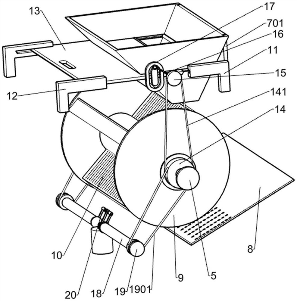
[0024] On the basis of Example 1, such as figure 2 As shown, the screening mechanism includes a leaking plate 8, a disc 9, a sieve plate 10 and a pulley 14. The leaking plate 8 is fixed on the rear side of the bottom in the working box 3, and the leaking plate 8 is located above the storage tank 28. Two pulleys 14 are respectively fixed on the inner side of the shaft rod one 5 near the pulley one 6, two discs 9 are fixed on the shaft rod one 5 near the inner side of the belt wheel two 14, and the four sieve plates 10 are fixed Connected to the upper middle part of the shaft one 5, the sieve plate 10 is fixedly connected with the disk 9.
[0025] When the corn grains enter the sieve plate 10 through the feeding device, the rotation of the shaft one 5 drives the rotation of the pulley two 14, the disc 9 and the sieve plate 10. During the rotation, the slightly smaller particles directly pass through the sieve. The small holes on the plate 10 fall into the receiving groove 28 t...
Embodiment 3
[0027] On the basis of Example 2, such as Figure 1-2 As shown, the feeding mechanism includes a hopper 7, a support column 2 701, a support plate 11, a support plate 12, a slide cover, a belt, a pulley 3 15, a shaft 2 16 and a swivel 17, and the hopper 7 is located in the working box 3. The upper side and the rear side of the hopper 7 are fixed with a plurality of support columns 2 701, the lower ends of the support columns 701 are fixed on the work box 3, and the two support plates 11 are fixedly connected to the left and right sides of the work box 3 respectively. , the two support plates 12 are respectively fixed on the left and right sides of the front part away from the support plate 11 of the working box 3, the slide plate 13 is slidably connected in the slide rails of the support plate 11 and the support plate 2 12, the slide plate 13 and the hopper 7 sliding connection, the left and right sides of the slide plate 13 are fixedly connected with a swivel 17, and the two ...
PUM
 Abstract
Description
Claims
Application Information
 - R&D
- Intellectual Property
- Life Sciences
- Materials
- Tech Scout
- Unparalleled Data Quality
- Higher Quality Content
- 60% Fewer Hallucinations
Browse by: Latest US Patents, China's latest patents, Technical Efficacy Thesaurus, Application Domain, Technology Topic, Popular Technical Reports.
© 2025 PatSnap. All rights reserved.Legal|Privacy policy|Modern Slavery Act Transparency Statement|Sitemap|About US| Contact US: help@patsnap.com


