Concrete vibrating leveling device

A concrete and spliced ​​technology, applied in construction, building structure, construction material processing and other directions, can solve the problems of inconvenient carrying or moving, large vibration motor quality, high labor cost, etc., to reduce the burden of transportation and improve the Work efficiency and labor saving effect

Inactive Publication Date: 2015-03-25
NANJING DENGYU MACHINERY EQUIP MFG CO LTD
View PDF6 Cites 11 Cited by
  • Summary
  • Abstract
  • Description
  • Claims
  • Application Information

AI Technical Summary

Problems solved by technology

When in use, it is necessary to insert the metal vibrating head into the concrete, transmit the vibration of the vibrating motor to the concrete through the vibrating tube, and continuously use the vibrating head to compact the concrete. However, the vibrating motor has a large mass and is inconvenient to carry or move. The concrete after vibration still needs to be leveled again, and the subsequent leveling is mostly done manually, which is labor-intensive, slow in use, and high in labor costs

Method used


Image

  • Concrete vibrating leveling device
  • Concrete vibrating leveling device
  • Concrete vibrating leveling device

Examples


Embodiment Construction

[0023] In order to make the technical means, creative features, goals and effects achieved by the present invention easy to understand, the present invention will be further described below in conjunction with specific illustrations.

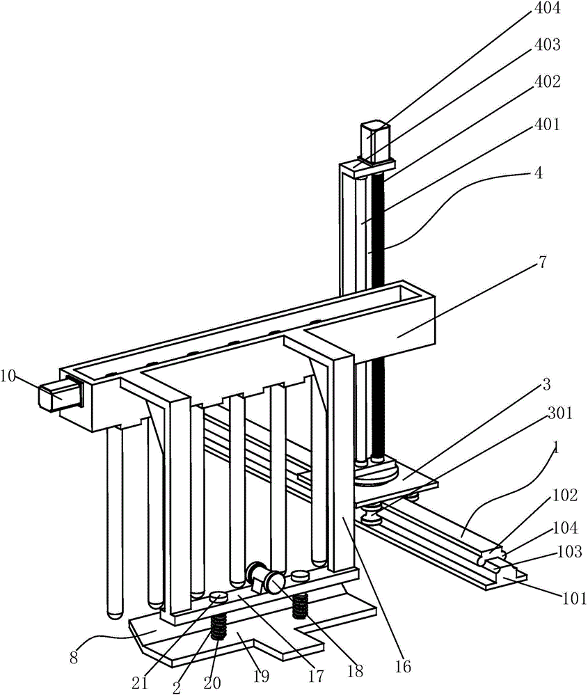
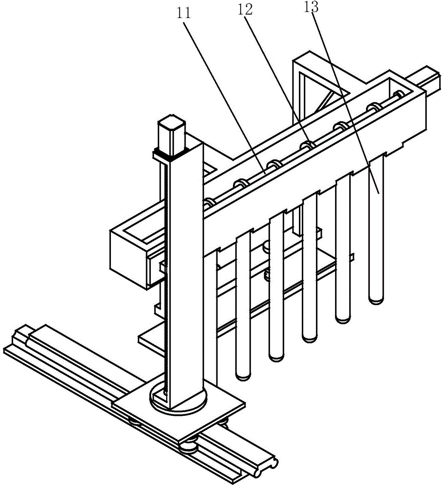
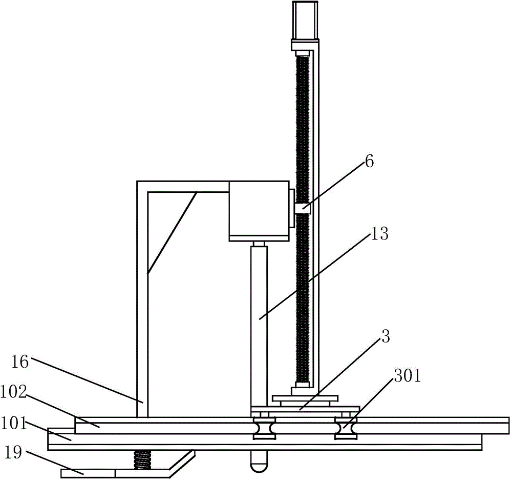
[0024] Such as Figure 1 to Figure 6 As shown, a concrete vibrating troweling device includes a spliced ​​track 1, and the spliced ​​track 1 includes a T-shaped base rail 101 and a pressure rail 102. The edges on the left and right sides of the upper end surface of the base rail 101 Each is provided with an arc-shaped concave surface 103, and the left and right sides of the lower end surface of the pressure rail 102 are respectively provided with a cylinder 104 matching the arc-shaped concave surface 103 on the base rail 101, and a slide plate 3 is arranged above the pressure rail 102, so that The lower surface of the slide plate 3 is provided with four pairs of rollers 301 corresponding to each other and stuck on the cylinder 104. The circumfer...


PUM


Abstract

The invention relates to a concrete vibrating leveling device which comprises a spliced rail. A sliding plate is arranged on the spliced rail, the lower end face of the sliding plate is provided with at least two rollers correspondingly clamped to the spliced rail, the upper end face of the sliding plate is fixedly provided with a positioning lifting frame, the positioning lifting frame comprises a guide rod and a lead screw, the upper end of the guide rod and the upper end of the lead screw are each fixedly provided with an upper end cap, the upper end caps are fixedly provided with a first motor, a shaft of the first motor is connected with the lead screw, the guide rod is provided with a left sliding sleeve, the lead screw is provided with a right sliding sleeve, a cam box is arranged in front of the left sliding sleeve and the right sliding sleeve, a second motor is fixed to the cam box, a shaft of the second motor is connected with transverse rods transversely arranged in the cam box, the transverse rods correspond to through holes and are each sleeved with an ejector rod cam, and vibration bars are arranged in the through holes in a penetrating mode. According to the device, concrete is tamped through the vibration bars by means of the ejector rod cams fixed to the transverse rods, tamping efficiency of the vibration bars is improved, and the aim that vibration and tamping of the vibration bars are carried out at the same is achieved.

Description

technical field [0001] The invention relates to the technical field of mechanical equipment for construction, in particular to a vibrating smoothing device for concrete. Background technique [0002] With the rapid development of China's economy, various infrastructures are gradually improving, and engineering projects can be seen everywhere. Driven by infrastructure construction and urbanization, large-scale infrastructure construction will continue for quite a while. Judging from the development plans for railways, highways, airports, ports, water conservancy, energy, urban construction, housing construction, and new rural construction in the next 5 to 10 years, the construction scale and investment intensity are astonishing. Therefore, the use of construction equipment will continue to increase, and the requirements for the performance of construction equipment will be stricter. [0003] The concrete vibrator is a vibrating device used in order to prevent a large number ...

Claims


Application Information

Patent Timeline
Patent Type & Authority Applications(China)
IPC IPC(8): E04G21/08E04G21/10
Inventor 胡玉平
Owner NANJING DENGYU MACHINERY EQUIP MFG CO LTD
Why Eureka
Try Eureka