
Automatic slotting and grinding integrated equipment for machining electronic parts for communication

A technology for electronic parts and grinding, which is applied in metal processing equipment, grinding/polishing equipment, milling machine equipment, etc. The problem of low positioning effect of the device, to achieve the effect of convenient laser injection, improved service life, and convenient collection

Pending Publication Date: 2020-12-25
深圳市华博自动化设计有限公司
View PDF0 Cites 3 Cited by
  • Summary
  • Abstract
  • Description
  • Claims
  • Application Information

AI Technical Summary

Problems solved by technology

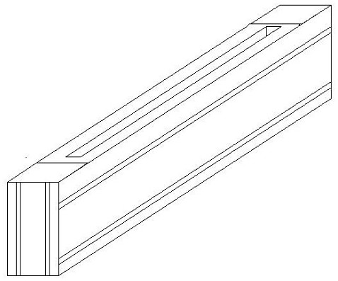
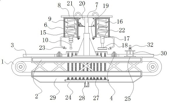
[0004] Aiming at the deficiencies of the prior art, the present invention provides an automatic slotting and grinding integrated equipment for the processing of electronic components for communication, which solves the problem that the existing socket parts cannot be simultaneously opened and finished when processing in the above-mentioned background technology. Grooving and grinding operations need to transfer the slot parts manually or by a conveyor belt, which is not conducive to improving work efficiency, and the positioning effect of the slotting device is not high, which may easily cause the finished slot parts to fail to meet the qualified standards, resulting in waste of resources

Method used


Image

  • Automatic slotting and grinding integrated equipment for machining electronic parts for communication
  • Automatic slotting and grinding integrated equipment for machining electronic parts for communication
  • Automatic slotting and grinding integrated equipment for machining electronic parts for communication

Examples


Embodiment Construction

[0025] The following will clearly and completely describe the technical solutions in the embodiments of the present invention with reference to the accompanying drawings in the embodiments of the present invention. Obviously, the described embodiments are only some, not all, embodiments of the present invention.

[0026] In the description of the present invention, unless otherwise stated, the meaning of "plurality" is two or more; the terms "upper", "lower", "left", "right", "inner", "outer" , "front end", "rear end", "head", "tail", etc. indicate the orientation or positional relationship based on the orientation or positional relationship shown in the drawings, and are only for the convenience of describing the present invention and simplifying the description, rather than Indicates or implies that the device or element referred to must have a particular orientation, be constructed and operate in a particular orientation, and therefore should not be construed as limiting the...


PUM


Abstract

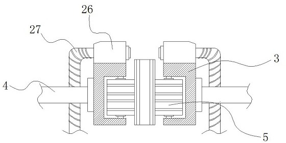
The invention discloses automatic slotting and grinding integrated equipment for machining electronic parts for communication, and relates to the technical field of automatic slotting and grinding integrated equipment. In particular, the equipment comprises a conveying belt, a slotting and grinding mechanism and arraying mechanisms, wherein bearing platforms are arranged on the two sides of the conveying belt, and guide plates are arranged on the two sides of the upper portion of the conveying belt. Electric push rods are connected to the sides, away from the central axis of the conveying belt, of the guide plates, the bottoms of the electric push rods are connected with the surfaces of the bearing platforms, clamping roller sets are arranged in the guide plates, and the arraying mechanisms are arranged at the right ends of the surfaces of the bearing platforms. According to the automatic slotting and grinding integrated equipment for machining the electronic parts for communication, alaser pen generates a laser beam to irradiate the surface of a slot piece, so that the cutting position is determined, and the accuracy of the slotting position is improved; and a transparent crystalforms an elastic structure through an extensible spring, chippings can be discharged from the interior of a slotting milling cutter in the later period conveniently, foreign matter is prevented fromentering the slotting milling cutter, and meanwhile the laser beam is prevented from being blocked.

Description

technical field [0001] The invention relates to the technical field of automatic slotting and grinding integrated equipment, in particular to an automatic slotting and grinding integrated equipment for processing electronic components for communication. Background technique [0002] The socket is an important electronic component in various communication equipments, and it has the advantages of clamping and fixing, reading and detection, and easy disassembly and assembly. The socket is basically long and has a slot on its surface, which is convenient For the insertion of other electronic components, the existing processing method of the slot part basically uses a cutting saw blade to grooving the surface, and then polishes the burr with a grinding device, and then adds and reads other components inside the slot of the slot part. Electronic components for devices. [0003] When the existing slot parts are processed, the slotting and grinding operations cannot be completed at...

Claims


Application Information

Patent Timeline
Patent Type & Authority Applications(China)
IPC IPC(8): B23C3/30B23Q11/00B24B9/04B24B19/02B24B41/00B24B41/04B24B47/12B24B55/03B24B55/06
CPCB23C3/30B23Q11/0042B24B9/04B24B19/02B24B41/005B24B41/04B24B47/12B24B55/03B24B55/06
Inventor 黄军梅李耀永邝润森
Owner 深圳市华博自动化设计有限公司
Learn More