Semi-formed wooden barrel bottom surface grinding device
A bottom surface and flattening technology, which is applied in the direction of grinding drive devices, grinding/polishing safety devices, grinding machines, etc., can solve the problems of high labor intensity, low efficiency, and the accuracy of grinding machines that are easy to cut the arm, and achieve reduction The effect of labor intensity
- Summary
- Abstract
- Description
- Claims
- Application Information
AI Technical Summary
Problems solved by technology
Method used
Image
Examples
Embodiment 1
[0062] A kind of semi-formed barrel bottom grinding device, such as figure 1 , figure 2 , Figure 4 and Figure 6 As shown, it includes a base 1, a workbench 2, an operation table 3, a power motor 4 and a grinding mechanism 5. A workbench 2 is arranged on the top of the base 1, and a power motor 4 is installed on the right side of the top of the workbench 2. The top of the workbench 2 An operating table 3 is provided, the power motor 4 is located at the same level as the operating table 3, and a grinding mechanism 5 is provided on the top of the working table 2.
[0063]People can use the present invention to grind the bottom surface of the wooden barrel. First, people place the wooden barrel that needs to be cut on the console 3, then start the power motor 4, and the power motor 4 will drive the grinding mechanism 5 to start running. Wooden barrel is cut, after grinding mechanism 5 cuts wooden barrel ground smooth, closes power motor 4, takes off wooden barrel.
Embodiment 2
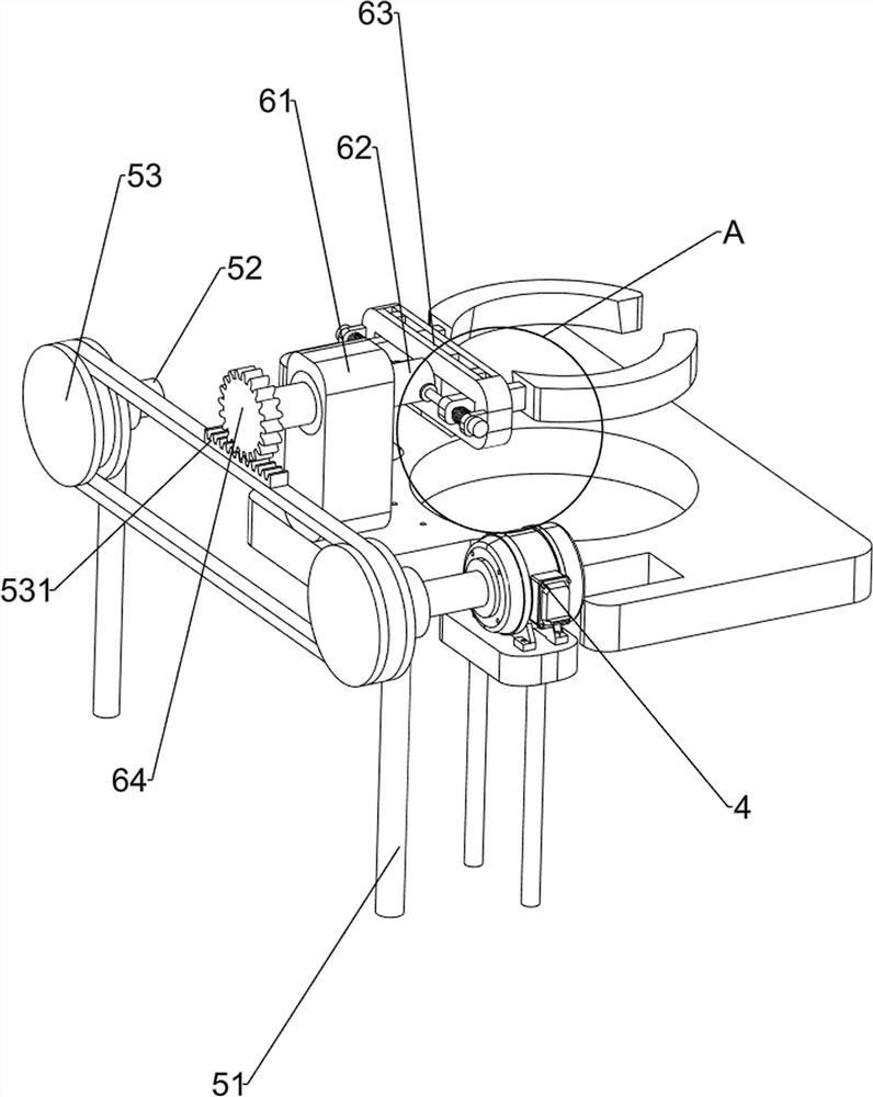
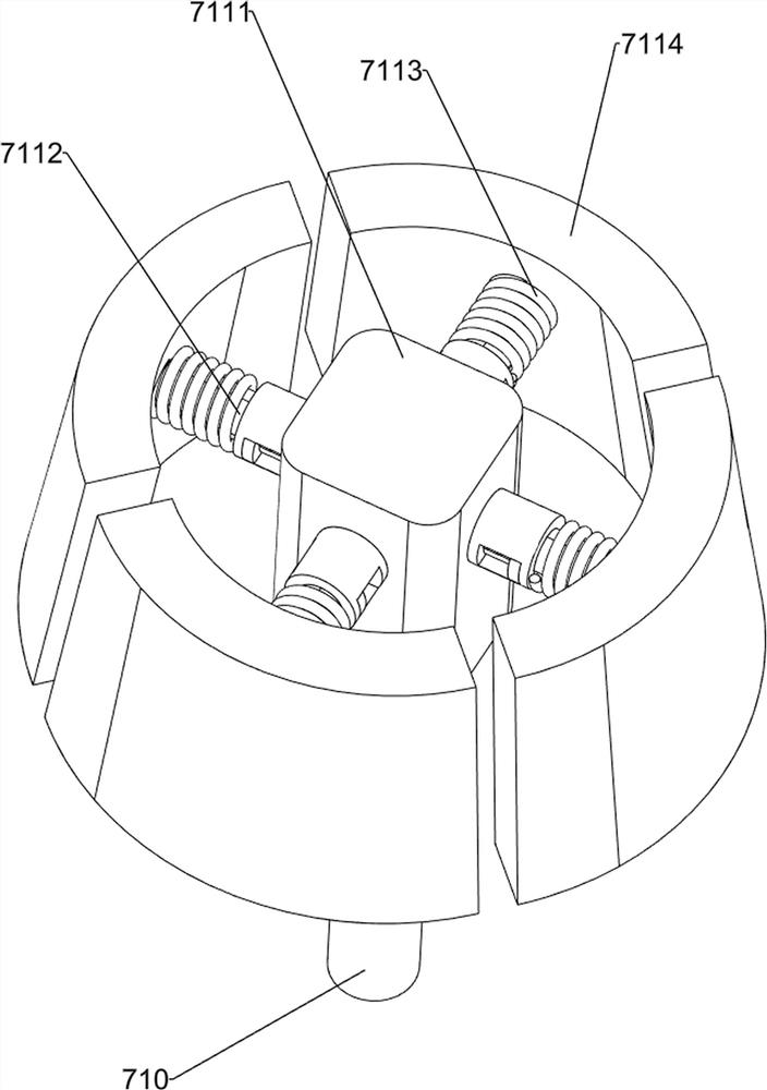
[0065] On the basis of Example 1, such as figure 2 , image 3 , Figure 4 As shown, the grinding mechanism 5 includes a first column sleeve 51, a first rotating shaft 52, a first belt device 53, a parallel rack 531, a second column sleeve 54, a second rotating shaft 55, a third column sleeve 56, a second Belt device 57, missing gear 58, first guide block 59, vertical rod 591, ruler wedge block 510, triangular wedge block 511, grinding device 512, first guide column 513 and first compression spring 514, workbench 2 top left and right Both sides are provided with the first column sleeve 51, the first column sleeve 51 top is rotatably provided with the first rotating shaft 52, the first belt device 53 is arranged between the first rotating shaft 52, the first rotating shaft 52 on the right side is connected with the power motor 4 The output shaft is connected, the first belt device 53 is provided with a parallel rack 531, the front side of the top of the workbench 2 is provide...
Embodiment 3
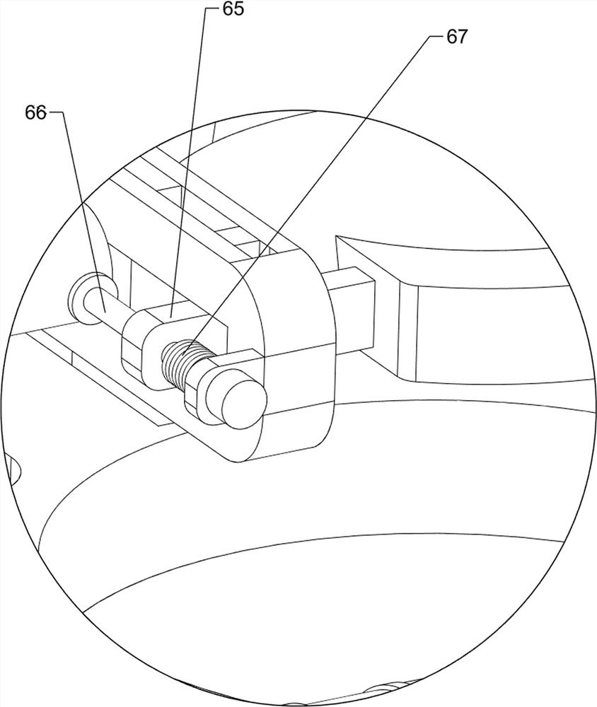
[0068] On the basis of Example 2, such as Figure 4 , Figure 5 , Figure 6 and Figure 7 As shown, the clamping steering mechanism 6 is also included, and the clamping steering mechanism 6 includes a fixed block 61, a rotating column 62, a second guide block 63, a spur gear 64, a moving block 65, a fixed guide column 66 and a second compression spring 67, the front side of the top of the workbench 2 is provided with a fixed block 61, the upper part of the fixed block 61 is rotatably provided with a rotating column 62, and the front side of the rotating column 62 is provided with a spur gear 64, the spur gear 64 meshes with the parallel rack 531, and the rotating column 62 The rear side is provided with a second guide block 63, and the left and right sides of the rear end of the rotating column 62 are provided with fixed guide posts 66. The fixed guide post 66 is slidably provided with a moving block 65, and the fixed guide post 66 slides in the second guide block 63. , The...
PUM
 Abstract
Description
Claims
Application Information
 - R&D
- Intellectual Property
- Life Sciences
- Materials
- Tech Scout
- Unparalleled Data Quality
- Higher Quality Content
- 60% Fewer Hallucinations
Browse by: Latest US Patents, China's latest patents, Technical Efficacy Thesaurus, Application Domain, Technology Topic, Popular Technical Reports.
© 2025 PatSnap. All rights reserved.Legal|Privacy policy|Modern Slavery Act Transparency Statement|Sitemap|About US| Contact US: help@patsnap.com


