
Automobile plastic part manufacturing method

A manufacturing method and spare parts technology, applied in the field of automobile plastic spare parts manufacturing, can solve the problems of burr adhesion and falling, affecting the later use effect of automobile plastic spare parts, multiple burrs, etc., and achieve the effect of preventing mess

Active Publication Date: 2020-12-25
柳州精特汽配制造有限公司
View PDF3 Cites 2 Cited by
  • Summary
  • Abstract
  • Description
  • Claims
  • Application Information

AI Technical Summary

Problems solved by technology

[0003] 1. Because the material of automotive plastic parts is relatively soft, it is not easy to fix the automotive plastic parts during the finishing process, so that when the outer surface of the automotive plastic parts is deburred and polished, the automotive plastic parts are fixed. Rotation occurs on the tool, resulting in poor deburring and grinding effect, which affects the post-use effect of automotive plastic parts;
[0004] 2. After the surface of the automotive plastic parts is polished, there are likely to be more polished burrs on the automotive plastic parts, which will cause the burrs to adhere and fall around when the automotive plastic parts are removed from the fixing fixture. messy workbench

Method used


Image

  • Automobile plastic part manufacturing method
  • Automobile plastic part manufacturing method
  • Automobile plastic part manufacturing method

Examples


Embodiment Construction

[0032] The embodiments of the present invention will be described in detail below with reference to the accompanying drawings, but the present invention can be implemented in many different ways as defined and covered by the claims.

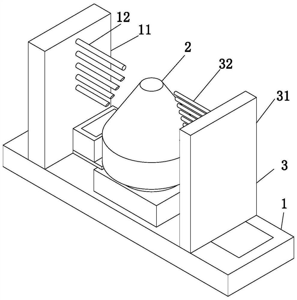
[0033] Such as Figure 1 to Figure 8Shown, a kind of automobile plastic spare parts manufacturing method, it has used a kind of finishing processing machine, and this machine comprises workbench 1, clamping mechanism 2 and grinding mechanism 3, and the middle part of the upper end face of described workbench 1 is installed with The clamping mechanism 2, the right side of the clamping mechanism 2 is provided with a grinding mechanism 3;

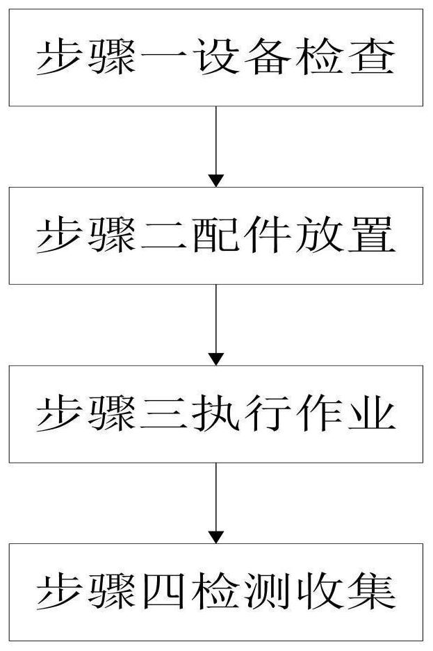
[0034] The method for producing and processing automobile plastic spare parts using the above-mentioned finishing machine includes the following steps;

[0035] Step 1: Equipment inspection, starting the finishing machine to check its operation, so that the finishing machine can successfully complete the process...


PUM


Abstract

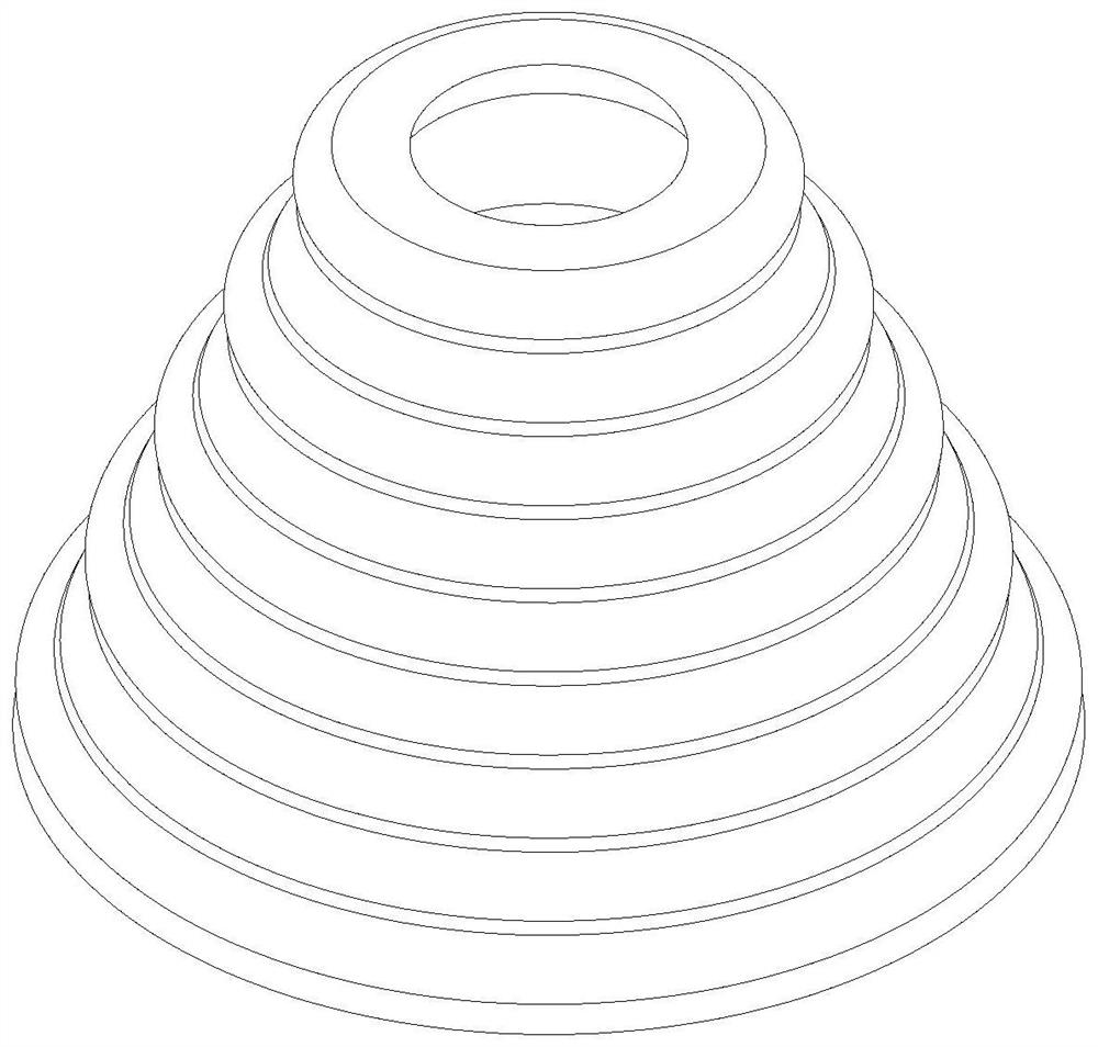
The invention relates to an automobile plastic part manufacturing method which uses a finishing machine. The finishing machine comprises a workbench, a clamping mechanism and a grinding mechanism, theclamping mechanism is arranged in the middle of the upper end surface of the workbench, and the grinding mechanism is arranged on the right side of the clamping mechanism. The clamping mechanism is adopted for clamping the interior of an automobile plastic part, the clamping mechanism is clamped into an internal thread groove of the automobile plastic part for corresponding clamping-in of the internal thread groove of the automobile plastic part, and the automobile plastic part is prevented from being disengaged from the workbench in the rotating polishing process; and the grinding mechanismis adopted to grind the surface of the automobile plastic part,grinding rods stretch out and draw back according to the surface shape of the automobile plastic part, so that the grinding rods are completely attached to the outer surface of the automobile plastic part, rubber layers are installed on the left end faces of fixing rods and the left end faces of clamping rods. and the phenomenon that the fixing rods and the clamping rods cause clamping damage to the automobile plastic part when clamping the automobile plastic part is prevented.

Description

technical field [0001] The invention relates to the technical field of auto parts, in particular to a method for manufacturing auto plastic parts. Background technique [0002] The definition of plastic is mainly composed of carbon, oxygen, hydrogen, nitrogen and other organic or inorganic elements. The finished product is a solid, and it is a molten liquid during the manufacturing process. Therefore, it can be melted by machine heating, pressured to make it flow, Cool it to solidify and form various shapes. This huge and varied material group is called plastic. Plastic refers to high molecular weight synthetic resin as the main component, adding appropriate additives, such as plasticizers, stabilizers, and barrier Fuels, lubricants, colorants, etc., processed plastic and flexible materials, or rigid materials formed by curing and cross-linking, plastic parts are widely used in every field of life today, such as household appliances, instruments, wires and cables, Construct...

Claims


Application Information

Patent Timeline
Patent Type & Authority Applications(China)
IPC IPC(8): B24B9/20B24B27/00B24B41/06B24B55/06B24B55/12B24B47/12B24B55/00
CPCB24B9/20B24B27/0076B24B41/06B24B41/067B24B47/12B24B55/00B24B55/06B24B55/12
Inventor 何芳芳
Owner 柳州精特汽配制造有限公司
Learn More