Rubber bushing edge grinding machine

A technology of rubber bushing and edging machine, applied in the field of rubber, can solve problems such as degumming

Inactive Publication Date: 2020-12-25
梁正耕
View PDF0 Cites 0 Cited by
  • Summary
  • Abstract
  • Description
  • Claims
  • Application Information

AI Technical Summary

Problems solved by technology

[0002] The bushings are mostly made of soft metal, rubber, nylon and non-metallic polymers, etc. The texture of these materials is relatively soft, and they are suitable for various harsh working environments to withstand vibration, friction and corrosion to protect the bushing. In order to increase the scope of application of the bushing, most of the bushings are covered with rubber materials, and they need to be polished during the processing of the rubber bushing to ensure a tight fit between the rubber and the bushing, but When grinding the edge of the bush, the high-intensity grinding action often causes the rubber bush to separate from the external rubber material and degumming, which causes the rubber material to float on the surface of the bush. Based on the above premise, a rubber bush was developed in this case. Edger to solve this problem

Method used


Image

  • Rubber bushing edge grinding machine
  • Rubber bushing edge grinding machine
  • Rubber bushing edge grinding machine

Examples


Embodiment

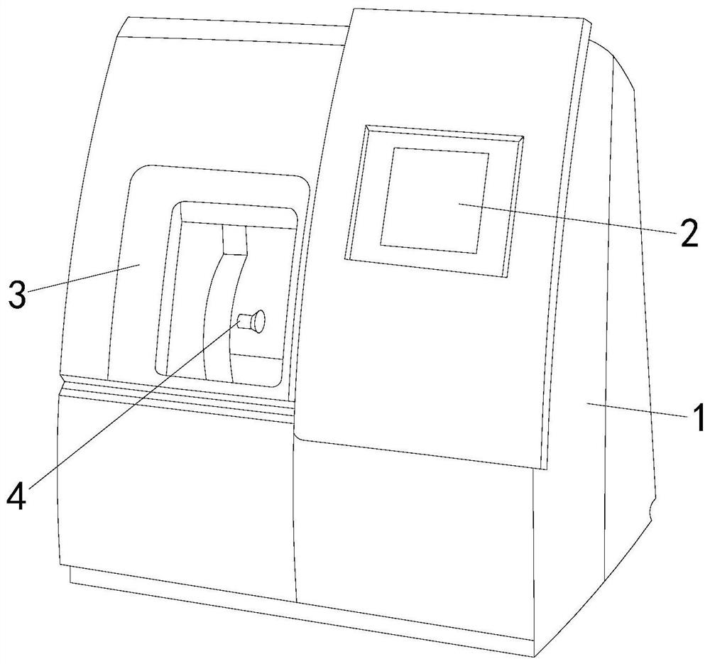
[0024] see figure 1 , the present invention provides a rubber bush edger, the structure of which includes: an edger frame 1, a control panel 2, an inspection window 3, and a grinding mechanism 4, and the side of the edger frame 1 is provided with a control panel 2 , the inspection window 3 is located on one side of the edging frame 1, the grinding mechanism 4 is located in the inspection window 3 and connected with the edging frame 1, the edging frame 1 is the main structure of the equipment, and on the one hand, it serves as the shell of the equipment The structure provides protection for other associated components. On the other hand, it serves as a carrier structure for equipment control elements to allow other structures to be installed on the equipment. The internal hollow structure layer formed based on the external box structure is used as a rubber bushing workpiece. In the processing platform area, the control panel 2 can realize the operation command and parameter ac...

Embodiment 2

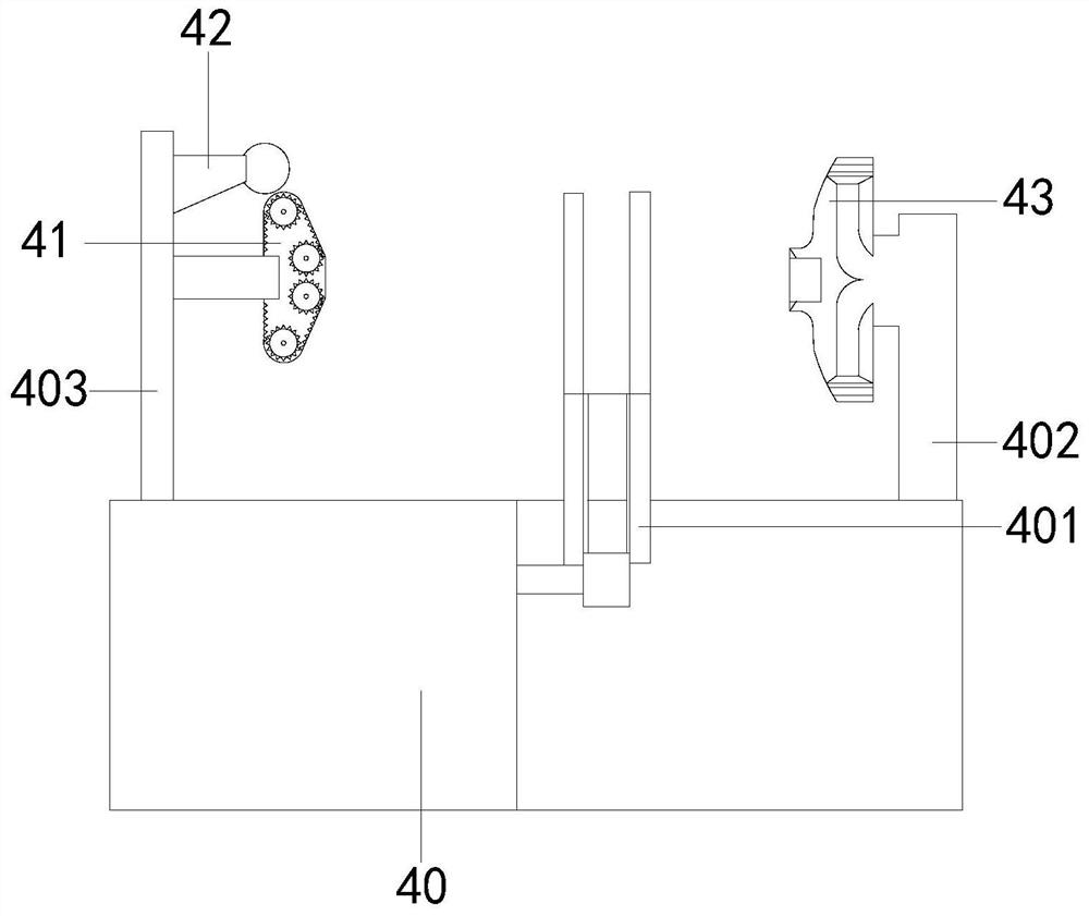
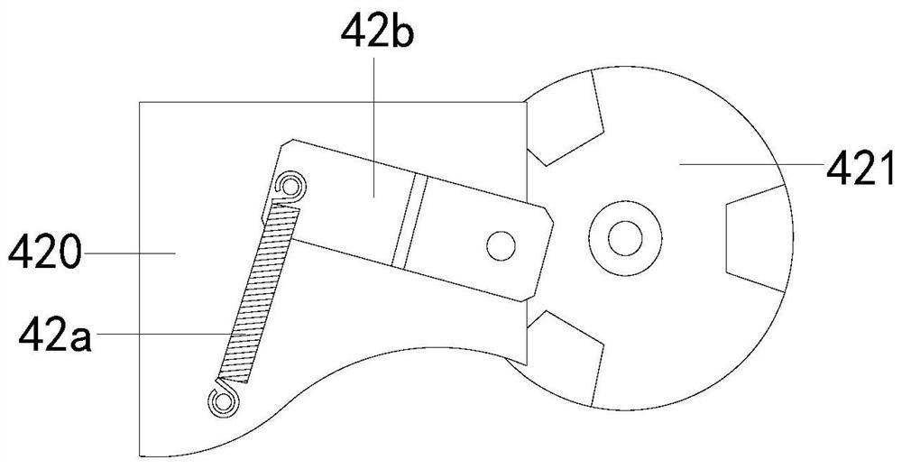
[0031] The description of the second embodiment drawn in conjunction with the first embodiment, combined with figure 2 , image 3 , Figure 5 and Figure 6 One side of the prime mover 40 is connected to a polishing disc 41, a lubricating wheel 42 is arranged at intervals above the polishing disc 41 and a cutting disc 43 is correspondingly provided on one side thereof, and one end of the swing seat 420 is fitted with an intermittent oiler 421 and the two are connected One end of the rotary cutting disc 430 is provided with a connection hole 431 and a chip removal groove 432 is opened on the back thereof. The body 4301 is externally connected to the scraper guide ring 4304. When processing the rubber bushing, the bushing is clamped and fastened by turning over the clamp rod 40 first, and the position of the end face is adjusted according to the processing requirements, and the rubber bushing is matched with the polishing disc 41 and the cutting disc 43. The edge of the sleev...


PUM


Abstract

The invention discloses a rubber bushing edge grinding machine. The machine structurally comprises an edge grinding machine frame, a control screen, an inspection window and a grinding mechanism, wherein the control screen is arranged on the side edge of the edge grinding machine frame, the inspection window is arranged on one side of the edge grinding machine frame, and the grinding mechanism islocated in the inspection window and connected with the edge grinding machine frame. The machine has the beneficial effects that a blade structure with rotary cutting wheel discs arranged in a layeredmode in a structure generates circumferential tangential motion in the rotating process to abut against an edge position of a rubber bushing to rapidly cut the rubber bushing, a conventional frictionmode is replaced with a cutting mode to polish the rubber bushing, the friction strength and the winding degree of the structure on the rubber bushing can be reduced, and a rubber material is effectively prevented from being separated from the bushing.

Description

technical field [0001] The invention relates to the field of rubber, in particular to a rubber bush edger. Background technique [0002] The bushings are mostly made of soft metal, rubber, nylon and non-metallic polymers, etc. These materials are relatively soft, and they are suitable for various harsh working environments to withstand vibration, friction and corrosion to protect the bushing. In order to increase the scope of application of the bushing, most of the bushings are covered with rubber materials, which need to be polished during the processing of the rubber bushing to ensure a tight fit between the rubber and the bushing, but When grinding the edge of the bushing, the high-intensity grinding action often causes the rubber bushing to separate from the outer rubber material and degumming, which causes the rubber material to float on the surface of the bushing. Based on the above premise, a rubber bushing was developed in this case. Edger to solve this problem. C...

Claims


Application Information

Patent Timeline
Patent Type & Authority Applications(China)
IPC IPC(8): B24B27/00B24B9/20B24B41/06B24B41/00B24B55/00B24B55/06B24D7/00B29C37/02
CPCB24B9/20B24B27/0076B24B41/005B24B41/06B24B55/00B24B55/06B24D7/00B29C37/02
Inventor 梁正耕
Owner 梁正耕
Why Eureka
Try Eureka