
Furnace End Face Sealing Structure for Perlite Expansion Furnace

An end face sealing and perlite technology is applied in the field of furnace end face sealing structures for perlite expansion furnaces, which can solve the problems of inconvenient disassembly and installation, inconvenient internal cleaning, economic loss, etc., and is suitable for popularization and use, and avoids the failure of sealing effect. , Stable and reliable effect

Active Publication Date: 2021-12-24
江苏奥纳麦格科技有限公司
View PDF0 Cites 0 Cited by
  • Summary
  • Abstract
  • Description
  • Claims
  • Application Information

AI Technical Summary

Problems solved by technology

[0003] Existing perlite expansion furnaces often adopt vertical expansion furnaces, and the furnace roof adopts a water-cooled structure, but the sealing structure at the end is often connected by a welded fixed end cover, which is inconvenient for internal cleaning and inconvenient It is inconvenient to disassemble and install. At the same time, the lower end also adopts a closed structure. Occasionally, the water sealing system is used to seal the lower part. However, due to the high residual temperature of the furnace bottom, the water in the water sealing system evaporates quickly. Rehydration must be carried out, and unnecessary economic loss will be caused if the rehydration is not timely. Therefore, we urgently need a furnace end face sealing structure for perlite expansion furnace to solve the above problems

Method used


Image

  • Furnace End Face Sealing Structure for Perlite Expansion Furnace
  • Furnace End Face Sealing Structure for Perlite Expansion Furnace
  • Furnace End Face Sealing Structure for Perlite Expansion Furnace

Examples


Embodiment 1

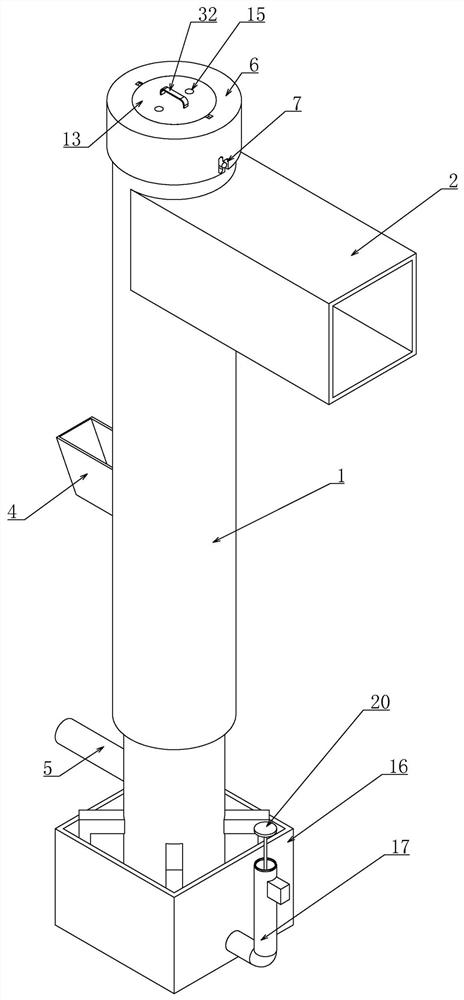
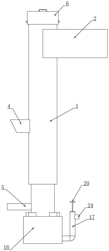
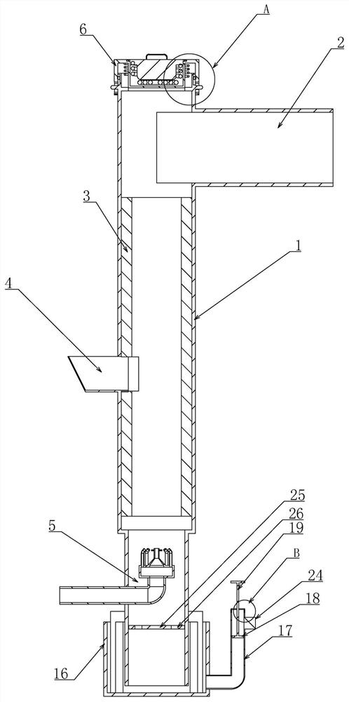
[0024]Embodiment 1, a furnace end face sealing structure for a perlite expansion furnace, comprising a furnace 1 with openings at the upper and lower ends of the furnace 1, characterized in that the upper end of the furnace 1 is connected to a discharge port 2, and the discharge port 2 is connected to a cyclone separator and After the dust collector, connect the silo, the outlet 2 is connected with an induced draft fan, and the induced draft fan is used to guide the expanded perlite to the outlet 2, and the furnace 1 is equipped with an insulation layer and Insulation layer 3, the heat insulation layer 3 blocks the high temperature in the furnace 1, and the insulation layer is to keep internal problems from being affected by the outside world, and the side wall of the furnace 1 is provided with a feed port 4, The feeding port 4 is opened at the position lower than the middle part of the side wall of the furnace 1, and the feeding port 4 is connected with a feeding hopper, and t...

Embodiment 2

[0025] Embodiment 2, on the basis of Embodiment 1 or 2, the water sealing device includes a water tank 16 connected to the lower end of the furnace 1, the inner bottom surface of the water tank 16 is not in contact with the lower bottom surface of the furnace 1, and the inside of the water tank 16 is connected to the lower end of the furnace. 1. The lower end is connected, and the lower end side wall of the water tank 16 is connected with a vertically arranged connecting pipe 17, which forms a connecting device structure with the water tank 16. The connecting pipe 17 is vertically slid to fit a float 18, and the The upper end of the buoy 18 is connected with a long connecting rod 19, and the upper end of the long connecting rod 19 is connected with a trigger plate 20. The size of the trigger plate 20 will cover the upper end of the connecting pipe 17, and the upper end of the connecting pipe 17 has an annular The accommodating groove 21, a trigger ring 22 is slid vertically in ...

Embodiment 3

[0027] Embodiment 3, on the basis of Embodiment 1 or 2, the end cap 13 includes two sets of limit pins 27 that are evenly distributed in the circumferential direction on the outer side wall of the end cap 13, and also includes two sets of stop pins 27 that are opened on the upper side wall of the accommodating cavity 12. Two groups of limit grooves 28 on the top are matched with corresponding side limit pins 27. The bottom of the limit groove 28 communicates with an arc-shaped arc groove 29 opened on the side wall of the receiving groove 21. The arc Shaped groove 29 cooperates with limit pin 27 to be used to limit the vertical relative movement of end cover 13, after end cover 13 is stuck in the bottom through the cooperation of limit groove 28 and limit pin 27, screw end cover 13, makes limit The position pin 27 snaps into the arc-shaped groove 29 to limit the vertical movement of the end cover 13 . The purpose of the movable connection of the end cover 13 is to facilitate mai...


PUM


Abstract

The invention relates to a furnace end face sealing structure for a perlite expansion furnace. The invention adopts a conveniently detachable sealing cover on the upper end of the furnace. When the furnace is not heated, the bayonet can cooperate with the lower end of the vertical groove to reduce the restoring force of the spring. Under the action of the action, the relative rotation between the sealing cover and the furnace is restricted, which is convenient for disassembly and installation, and the position of the sealing cover is stable and reliable, and the sealing effect is excellent. When the temperature in the furnace rises, under the action of air pressure, the card The pin cooperates with the upper end of the vertical groove to achieve clamping. The state of the sealing plate is stable and reliable when it is working. The sealing ring is used to increase the sealing effect at the same time. The lower end of the furnace adopts a water seal structure, and the movement of the float is used to realize the alarm when the water level drops to a dangerous height. The present invention is exquisite in conception and simple in operation, and the sealing cover at the end thereof has a good sealing effect and is convenient for disassembly and installation, so that users can clean the interior conveniently, has strong practicability, and is suitable for popularization and use.

Description

technical field [0001] The invention belongs to the technical field of perlite production equipment, in particular to a furnace end face sealing structure for a perlite expansion furnace. Background technique [0002] Expanded perlite is a kind of natural acidic vitreous volcanic lava, non-metallic minerals, including perlite, pitch rock and obsidian, the three are just different in crystal water content. Because its volume rapidly expands 4 to 30 times under the high temperature condition of 1000-1300 ℃, it is collectively called expanded perlite. Generally, the expansion ratio is required to be >7 to 10 times (obsidian >3 times, available), and the silica is about 70%. All are open pit mined. No beneficiation is required, just crushing and screening. Expanded perlite is a kind of white granular material with a honeycomb structure inside, which is made of perlite ore after preheating and instantaneous high-temperature roasting and expansion. The principle is: perl...

Claims


Application Information

Patent Timeline
Patent Type & Authority Patents(China)
IPC IPC(8): C04B20/06
CPCC04B20/06
Inventor 董爽
Owner 江苏奥纳麦格科技有限公司
Learn More