Concrete-filled steel tube bundle composite shear wall with internally-arranged composite confined concrete columns
A technology for confining concrete and CFST, which is applied to walls, buildings, building components, etc., can solve the problems of insufficient utilization of fiber reinforced composite pipes and concrete properties, complicated construction technology, poor seismic performance, etc., to improve the ultimate bearing capacity. Capacity and ductility index, good seismic performance, and the effect of improved shear resistance
- Summary
- Abstract
- Description
- Claims
- Application Information
AI Technical Summary
Problems solved by technology
Method used
Image
Examples
Embodiment 1
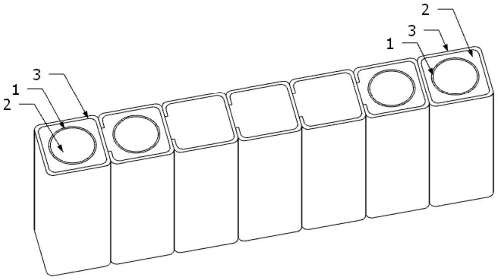
[0042] see figure 1 and figure 2 , this embodiment is an in-line steel tube bundle composite shear wall with built-in fiber-reinforced composite material tubes. A plurality of steel pipes 3 in the steel tube bundle are welded to each other in sequence, arranged in a line, at the wall end of the composite shear wall A fiber-reinforced composite material pipe 1 is arranged in the steel pipe 3 at the place. Among them, the fiber-reinforced composite material pipe 1 can be a carbon fiber-reinforced composite material pipe (referred to as CFRP pipe), a glass fiber-reinforced composite material pipe (referred to as GFRP pipe), an aramid fiber-reinforced composite material pipe (abbreviated as AFRP pipe), a basalt fiber pipe ( Referred to as BFRP pipe) in any one.
[0043] In order to further improve the mechanical performance of the shear wall, fiber-reinforced composite material pipes 1 are also arranged in the steel pipes 3 near both ends.
Embodiment 2
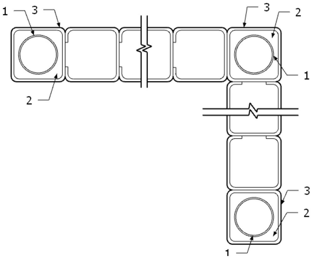
[0045] see image 3 and Figure 4 The difference between this embodiment and Embodiment 1 is that several steel pipes 3 of this embodiment are welded in sequence, and the steel pipe bundles are arranged in a special shape, such as an L-shaped arrangement or a T-shaped arrangement, that is, there are two walls. A fiber-reinforced composite material pipe 1 is respectively arranged in the steel pipe 3 at the end and at the intersection of two wall piers, and the other details are the same as in Embodiment 1.
Embodiment 3
[0047] see Figure 5 , the difference between this embodiment and embodiment 1 is that when the load is large, in order to meet the force requirements, the steel pipe 3 located at the end of the shear wall body can be enlarged, so that the size of the steel pipe 3 located here That is, the inner diameter is larger than that of the steel pipe 3 at other positions, and the steel pipe 3 here is defined as an end column, and the size of the fiber-reinforced composite material pipe 1 arranged in the end column, that is, the inner diameter, is also larger than that at other positions. In this way, the effect of further enhancing the bearing capacity and deformation capacity of the end of the composite shear wall of the steel tube concrete bundle can be achieved, and other details are the same as in Embodiment 1.
PUM
 Abstract
Description
Claims
Application Information
 - R&D
- Intellectual Property
- Life Sciences
- Materials
- Tech Scout
- Unparalleled Data Quality
- Higher Quality Content
- 60% Fewer Hallucinations
Browse by: Latest US Patents, China's latest patents, Technical Efficacy Thesaurus, Application Domain, Technology Topic, Popular Technical Reports.
© 2025 PatSnap. All rights reserved.Legal|Privacy policy|Modern Slavery Act Transparency Statement|Sitemap|About US| Contact US: help@patsnap.com


