Aluminum alloy door with fireproof function
An aluminum alloy and functional technology, which is applied in the field of aluminum alloy doors with fireproof function, can solve the problems of fast closing of the door body and affect the service life of aluminum alloy doors, etc., and achieve the effect of improving fireproof performance, increasing service life and avoiding height fixation
- Summary
- Abstract
- Description
- Claims
- Application Information
AI Technical Summary
Problems solved by technology
Method used
Image
Examples
Embodiment 1
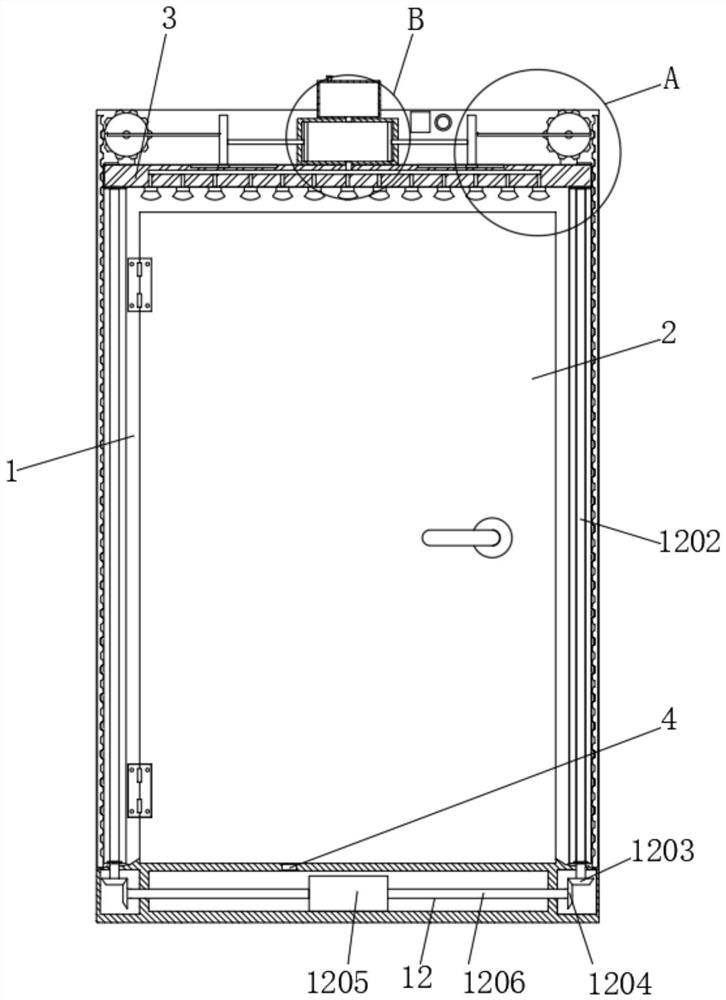
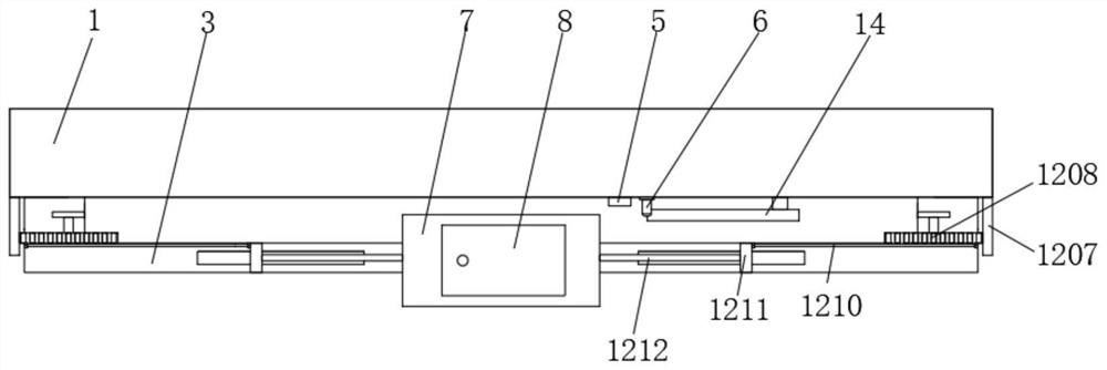
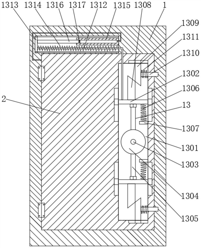
[0024] refer to Figure 1-6 , an aluminum alloy door with a fireproof function, comprising a door frame 1, a door body 2, a U-shaped bracket 3, a temperature sensor 4, a control panel 5, an alarm 6, a cold water cylinder 7, a water storage tank 8, a water inlet pipe 9, and a water outlet pipe 10. Nozzle 11, fire extinguishing mechanism 12, guide seat 1201, screw 1202, bevel gear 1 1203, bevel gear 2 1204, biaxial motor 1205, drive shaft 1206, fixed rack 1207, gear 1208, support block 1209, push-pull rod 1 1210, push-pull block 1211, piston rod one 1212, piston plate 1213, buffer mechanism 13, cavity 1301, movable plate 1302, rotating shaft 1303, turntable 1304, movable rod 1305, spring one 1306, fixed block 1307, resist rod one 1308, Resist rod 2 1309, post 1310, spring 2 1311, steel wire rope 1312, movable block 1313, spring 3 1314, fixed cylinder 1315, piston rod 2 1316, piston head 1317, connecting plate 1318, wave-shaped telescopic air bag 1319 and handle 14, The inside o...
Embodiment 2
[0027] refer to figure 1 , 2, 5 and 6, a fire extinguishing mechanism 12 is connected between the u-shaped bracket 3 and the door frame 1, the fire extinguishing mechanism 12 includes two symmetrical guide seats 1201 fixed on the u-shaped bracket 3, and the front end of the door frame 1 is provided with a guide seat 1201 matching guide grooves, the insides of the two guide seats 1201 are threadedly connected with screw rods 1202 respectively, the external threads on the two screw rods 1202 rotate in opposite directions, and the two ends of the screw rods 1202 are respectively rotated and connected to the inner wall sides of the guide grooves, two The bottom of the guide groove is respectively provided with an inner chamber 1 opened in the door frame 1, and one end of the two screw rods 1202 extends into the two inner chambers respectively, and is fixed with a bevel tooth 1203, and one side of the two bevel teeth 1203 Bevel teeth 2 1204 are engaged and connected respectively, ...
Embodiment 3
[0030] refer to image 3 and 4 A buffer mechanism 13 is installed between the door frame 1 and the door body 2. The buffer mechanism 13 includes a cavity 1301 provided inside the door body 2. Two movable plates 1302 are slidably connected to the inside of the cavity 1301. Between the two movable plates 1302 There is a rotating shaft 1303 rotatably connected to the inner front wall of the cavity 1301. One end of the rotating shaft 1303 extends to the positive end surface of the door body 2, and a handle 14 is fixed on it. The outer side of the rotating shaft 1303 is fixedly sleeved with a turntable 1304. The rear end face is hinged with two symmetrical movable rods 1305, one side of the movable rod 1305 is provided with a spring one 1306 fixed on the movable plate 1302, the other end of the spring one 1306 is fixed with a fixed block 1307, and the fixed block 1307 is fixed on the hollow On the inner wall of the cavity 1301, the opposite sides of the two movable plates 1302 are...
PUM
 Abstract
Description
Claims
Application Information
 - R&D
- Intellectual Property
- Life Sciences
- Materials
- Tech Scout
- Unparalleled Data Quality
- Higher Quality Content
- 60% Fewer Hallucinations
Browse by: Latest US Patents, China's latest patents, Technical Efficacy Thesaurus, Application Domain, Technology Topic, Popular Technical Reports.
© 2025 PatSnap. All rights reserved.Legal|Privacy policy|Modern Slavery Act Transparency Statement|Sitemap|About US| Contact US: help@patsnap.com


