

Threaded clamping and pressing type pipe structure and using method thereof
A compression-type pipe fitting and thread technology, which is applied in the direction of pipe/pipe joint/pipe fitting, through element, sealing surface connection, etc., can solve the problems of large wear of O-ring rubber ring, loss of rebound ability of gasket, and shortened service life. , to achieve the effect of high tensile strength, excellent temperature resistance and long service life
- Summary
- Abstract
- Description
- Claims
- Application Information
AI Technical Summary
Problems solved by technology
Method used
Image

Examples
Embodiment 1
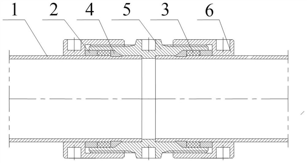
[0078] Such as Figure 1-4 As shown, a thread clamping pipe fitting structure includes a joint body 5, a pipe body 1, a nut 6 and a sealing assembly;
[0079] The joint body 5 includes a pipe body accommodation section and a seal assembly accommodation section; the pipe body 1 accommodation section is provided with a positioning spigot, and the seal assembly accommodation section is provided with a seal assembly accommodation cavity; the outer wall of the seal assembly accommodation section is provided with an external thread , the accommodating section of the sealing assembly is threadedly connected with the nut 6; the sealing assembly is placed in the accommodating chamber of the sealing assembly; in the accommodating chamber of the sealing assembly of the joint body 5, along the axial direction of the joint body 5, a cone is set away from the end of the nut 6 section, the seal assembly includes pressure ring 2, packing seal ring 3 and cone ring 4 arranged in sequence; cone ...
Embodiment 2
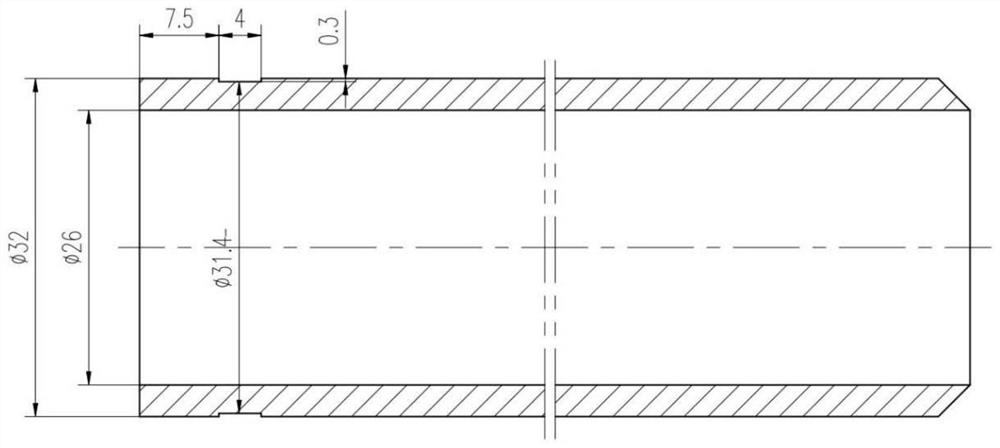
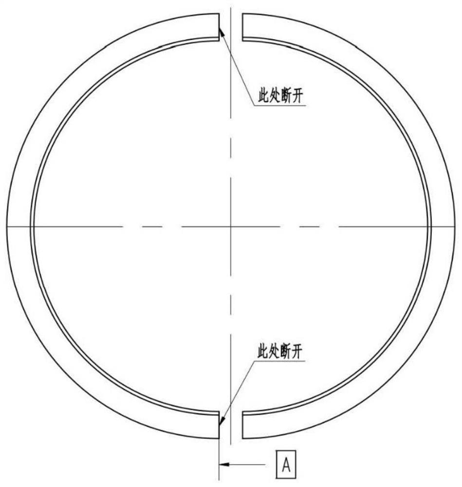
[0096] Compared with Example 1, it is only different in pipe diameter D, annular groove depth t, and annular groove width d, specifically, as Figure 2-3 As shown, pipe diameter D=32mm, annular groove depth t=0.3mm, annular groove width d=4.0mm, such as Figure 4 As shown, the size of the tapered ring matches the annular groove. Using the same test conditions and standards as in Example 1, the sealing device equipped with a φ32×1.2 pipe body is tested, and it still meets the service conditions under a pulling force of 25kN, and the sealing device has no leakage or falling off.
Embodiment 3
[0098]Compared with Example 1, it is only different in pipe diameter D, annular groove depth t, and annular groove width d, specifically, pipe diameter D=50.8mm, annular groove depth t=0.4mm, annular groove width d=6.0mm, for the performance test of the sealing device after the nut is tightened, the same test conditions and standards as in Example 1 are adopted, and the sealing device equipped with a φ50.8×1.2 pipe body is tested. Meet the conditions of use, and the sealing device has no leakage or falling off.
[0099] For pipes with a pipe diameter between 22-57mm, the sealing device of the present invention is used. After testing, the tensile strength is significantly higher than the standard requirement. The tensile force can reach 150%-200% of the standard requirements. As shown in Table 1, under the test tensile force of 150%-200% of the tensile force standard requirements, the sealing device has no leakage and no shedding. It should be noted that the table The tensile ...
PUM
 Abstract
Description
Claims
Application Information