High-brightness green light source device based on rod-shaped light conversion material

A technology of light conversion material and light source device, which is applied to optical elements, projection devices, lighting devices, etc. for changing the spectral characteristics of emitted light, can solve the problems of high cost, sudden drop in efficiency, low power density, etc. Reflection loss, improved luminous intensity, small ceramic end face effect

Active Publication Date: 2020-12-25
XUZHOU NORMAL UNIVERSITY
View PDF6 Cites 1 Cited by
  • Summary
  • Abstract
  • Description
  • Claims
  • Application Information

AI Technical Summary

Problems solved by technology

However, there are some unavoidable problems: 1) As the most widely used pump source in solid-state lighting, blue LEDs have inherent characteristics of sudden drop in efficiency and low power density (<2W / mm2) that limit their integration and miniaturization ; 2) LED side pumping is adopted, and the blue light is evenly irradiated, which will lead to the reabsorption of fluorescence away from the output end face, such as document 3 (Low Etendue Yellow-Green Solid-State Light Generation by Laser-pumped LuAG: Ce Ceramic), there are also similar 3) In the two literatures, the coating scheme is selected to improve the absorption rate of blue light and the utilization rate of yellow light, and the cost is relatively high

Method used


Image

  • High-brightness green light source device based on rod-shaped light conversion material
  • High-brightness green light source device based on rod-shaped light conversion material

Examples


Embodiment 1

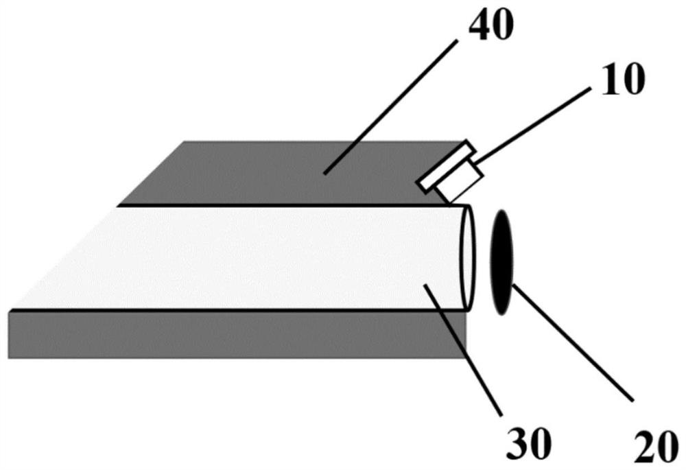
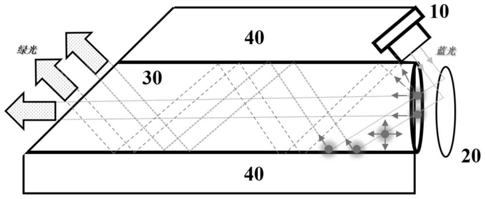
[0025] A high-brightness green light source device based on rod-shaped light conversion materials, such as figure 1 As shown, it includes a laser 10, a reflector 20, a fluorescent conversion rod 30, and a heat dissipation substrate 40; wherein,

[0026] The laser 10 is obliquely placed above the right end face of the fluorescent conversion rod 30, the angle between the light output direction of the laser 10 and the horizontal plane is 30°, and the spot radius of the laser 10 incident on the surface of the mirror 20 is 0.5mm; 20 is located on the right side of the fluorescent conversion rod 30, the radius of the reflector 20 is 6.0 mm, the distance between the reflective mirror 20 and the right end of the fluorescent conversion rod 30 is 1.0 mm, the fluorescent conversion rod 30 is cylindrical, and the left end surface is polished Slope, the direction of the polished slope is perpendicular to the light output direction of the laser, that is, the angle between the polished slope...

Embodiment 2

[0030] A high-brightness green light source device based on a rod-shaped light conversion material, including a laser 10, a reflector 20, a fluorescent conversion rod 30, and a heat dissipation base 40; wherein,

[0031] The laser 10 is obliquely placed above the right end face of the fluorescent conversion rod 30, the angle between the light output direction of the laser 10 and the horizontal plane is 40°, and the spot radius of the laser 10 incident on the surface of the mirror 20 is 1.0mm; 20 is located on the right side of the fluorescent conversion rod 30, the radius of the reflector 20 is 10.0 mm, the distance between the reflective mirror 20 and the right end of the fluorescent conversion rod 30 is 5.0 mm, the fluorescent conversion rod 30 is cylindrical, and the left end surface is polished Slope, the direction of the polished slope is perpendicular to the light output direction of the laser, that is, the angle between the polished slope and the horizontal plane is 50°,...

Embodiment 3

[0035] A high-brightness green light source device based on a rod-shaped light conversion material, including a laser 10, a reflector 20, a fluorescent conversion rod 30, and a heat dissipation base 40; wherein,

[0036]The laser 10 is placed obliquely above the right end face of the fluorescent conversion rod 30, the angle between the light output direction of the laser 10 and the horizontal plane is 33.3°, and the spot radius of the laser 10 incident on the surface of the reflector 20 is 0.8mm; The reflector 20 is located on the right side of the fluorescence conversion rod 30, the radius of the reflector 20 is 6.0 mm, and the distance between the reflector 20 and the right end of the fluorescence conversion rod 30 is 2.0 mm; the fluorescence conversion rod 30 is cylindrical, The left end face is a polished slope, and the direction of the polished slope is perpendicular to the light emitting direction of the laser, that is, the angle between the polished slope and the horizon...


PUM

PropertyMeasurementUnit
radiusaaaaaaaaaa
lengthaaaaaaaaaa
luminous fluxaaaaaaaaaa

Abstract

The invention discloses a high-brightness green light source device based on a rod-shaped light conversion material. The high-brightness green light source device comprises a laser, a reflecting mirror, a fluorescence conversion rod and a heat dissipation substrate; the laser is obliquely arranged above the right end surface of the fluorescence conversion rod, and the included angle between the light emitting direction of the laser and the horizontal plane is 30-40 degrees; the reflecting mirror is arranged on one side of the right end face of the fluorescence conversion rod, the distance between the reflector and the right end of the fluorescence conversion rod ranges from 1.0 mm to 5.0 mm, the fluorescence conversion rod is cylindrical, the left end face of the fluorescence conversion rod is a polishing inclined face, and the direction of the polishing inclined face is perpendicular to the light emitting direction of the laser. The laser and the fluorescence conversion rod are arranged in the heat dissipation substrate and are tightly attached to the heat dissipation substrate, the left end face of the heat dissipation substrate is an inclined face, and the inclination angle is the same as that of the left end face of the fluorescence conversion rod. The light conversion material with the polished inclined surface is adopted, the total reflection effect and the light-emittingsymmetry of a traditional vertically polished light material are broken through, and the green light output efficiency of the light conversion material and the light-emitting efficiency of a light source are greatly improved.

Description

technical field [0001] The invention relates to the technical field of laser display, in particular to a high-brightness green light source device based on a rod-shaped light conversion material. Background technique [0002] Laser display technology (Laser display technique, LDT) has significant advantages such as rich colors, high saturation, and strong contrast, and is widely considered to be the mainstream technology for future high-end displays such as large-screen projection, laser TV, and mobile phone projection. Its color gamut coverage can reach more than 90% of the color space that can be recognized by the human eye, and it can most truly reproduce the rich and gorgeous colors of the objective world. It is called "a revolution in the history of human vision". Laser display mainly has two forms: projection type and scanning type. The core backlight source is mainly three primary color light sources, namely blue light, green light and red light. Among them, green li...

Claims


Application Information

Patent Timeline
Patent Type & Authority Applications(China)
IPC IPC(8): G03B21/20G03B21/16F21V7/00F21V9/32F21V19/00
CPCF21V7/00F21V19/00F21V9/32G03B21/16G03B21/204G03B21/2066
Inventor 张乐康健陈东顺邵岑周天元王骋李明李延彬陈浩
Owner XUZHOU NORMAL UNIVERSITY
Why Eureka
Try Eureka